EVCO EC3162 User Manual
Ec 3-162
EC 3-162
EC 3-162
EC 3-162
EC 3-162
EC 3-162
Digital thermometer with two measure inputs
Operating instructions
Release 1/98 of December the seventh 1998
Code EC 3-162 DOC E000
File 3162e.p65
IMPORTANT:
The use of this new instrument is easy; but for safety reasons, it is
important read these instructions carefully before the installation or
before the use and follow all additional informations.
It is very important keep these instructions with the instrument for future
consultations.
ENGLISH
GENERAL INFORMA
GENERAL INFORMA
GENERAL INFORMA
GENERAL INFORMA
GENERAL INFORMATIONS
TIONS
TIONS
TIONS
TIONS
WHAT IS THE USE
EC 3-162 is a digital thermometer with two measure inputs able to cover a temperature range
from -50 to +150
°
C (-58 to +302
°
F).
In factory the instrument gets preset to accept at the measure inputs PTC probes used in this
field of applications at the moment; through the key present on the instrument frontal panel it
is possible to select the modality with which to display the temperatures read by the probes
(automatic or manual).
EC 3-162 is available in the 74 x 32 mm (2.91 x 1.25 in.) case and it is studied for panel
mounting with the equipped screw or spring brackets.
GETTING ST
GETTING ST
GETTING ST
GETTING ST
GETTING STAR
AR
AR
AR
ARTED
TED
TED
TED
TED
INSTALLATION
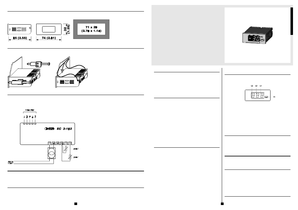
EC 3-162 was studied for panel mounting, panel cutout 71 x 29 mm (2.79 x 1.14 in.), with the
equipped screw or spring brackets (the overall dimensions and the panel cutout are related in
Fig. 3, the fixing systems suggested by the builder are related respectively in Fig. 4 and in
Fig. 5).
ADDITIONAL INFORMATIONS
-
the panel thickness must be included from 1 to 5 mm (0.04 to 0.19 in.)
-
verify if the using conditions (ambient temperature, humidity, etc.) are within the
limits indicated by the builder (see the chapter TECHNICAL DATA)
-
install the instrument in a location with a suitable ventilation, to avoid the inter-
nal overheating of the instrument
-
do not install the instrument near surfaces that can to obstruct the air-grating
(carpets, covers, etc.), heating sources (radiators, hot air ducts, etc.), locations
subject to direct sunlight, rain, humidity, excessive dust, mechanical vibrations
or bumps, devices with strong magnetos (microwave ovens, big speakers, etc.)
-
according with the safety norms, the protection against possible contacts with
electrical parts and parts protected with functional insulation only must be ensured
through a correct installation procedure of the instrument; all parts that ensure
the protection must be fixed so that they can not be removed if not with a tool
-
if not differently specified at the time of order, the instrument will be equipped
with screw brackets.
ELECTRICAL CONNECTION
EC 3-162 is provided with one screw terminal block for cables up to 2.5 mm² (0.38 in.², for the
connection to the power supply and measure inputs) and it is provided with one five poles
single line male connector (for the connection to the CLONE configurer/cloner and RICS super-
vision systems), located on the instrument back panel (the connections to derive are related in
Fig. 6 and they are checkable on the polyester label stuck on the instrument case).
ADDITIONAL INFORMATIONS
-
if the instrument is brought from a cold to a warm location, the humidity may
condense inside the instrument; wait about an hour before supply the instrument
-
verify if the operating power supply voltage, electrical frequency and power of
the instrument correspond to the local power supply (see the chapter TECHNICAL
DATA)
-
do not supply more instruments with the same transformer
-
if the instrument is installed on a vehicle, its power supply must be derived di-
rectly from the battery of the vehicle
-
give the instrument a protection able to limit the current absorbed in case of
failure
-
the instrument remains connected to the local power supply as long as the termi-
nals 7 and 8 are derived to the local power supply, even if the instrument is appar-
ently turned off
-
give the probes a protection able to insulate them against possible contacts with
metal parts or use insulated probes
-
do not try to repair the instrument; for the repairs apply to highly qualified staff
-
if you have any questions or problems concerning the instrument please consult
Fig. 1
f3-162.wmf
Every Control (see the chapter BUILDER DATA).
USE
USE
USE
USE
USE
PRELIMINARY INFORMATIONS
After derived the connections related in Fig. 6, during the normal functioning the instrument
displays the temperatures read by the probes.
Fig. 2
iu3162.wmf
If an alarm should be active the instrument displays the alarm code flashing as long as the
cause that has given it does not disappear (see the chapter SIGNALS AND ALARMS).
EC 3-162 is provided with two modality with which to display the temperatures read by the
probes (automatic and manual, see the paragraphs SELECTION OF THE MODALITY, AUTO-
MATIC MODALITY and MANUAL MODALITY).
The LED L1 is associated to the probe 1, it is turned ON during the display of the temperature
read by the probe 1 and it is turned OFF during the display of the temperature read by the
probe 2.
The LED L2 is associated to the probe 2, it is turned ON during the display of the temperature
read by the probe 2 and it is turned OFF during the display of the temperature read by the
probe 1.
The LED L3 is associated to the modality with which to display the temperatures read by the
probes, it is turned ON during the automatic modality and it is turned OFF during the manual
modality.
SELECTION OF THE MODALITY
To select a modality keep pushed for four seconds at least the key T1 (passed four seconds the
LED L3 turning ON or turning OFF).
ADDITIONAL INFORMATIONS
-
for the whole period of a corrupted memory data alarm the selection of the modality
with which to display the temperatures read by the probes is refused
-
the selected modality gets stored in a non volatile memory even if a lack of power
supply happens.
AUTOMATIC MODALITY
The instrument displays the temperature read by the probe 1 alternated to the temperature
read by the probe 2.
ADDITIONAL INFORMATIONS
-
the temperature read by a probe gets displayed for five seconds.
MANUAL MODALITY
The instrument displays the temperature read by the probe 1.
To display the temperature read by the probe 2 push and release the key T1 (to the release of
the key T1 the LED L1 turning OFF and the LED L2 turning ON).
To display the temperature read by the probe 1 again push and release the key T1 (to the
release of the key T1 the LED L1 turning ON and the LED L2 turning OFF).
ADDITIONAL INFORMATIONS
-
the selection of the temperature read by a probe gets stored in a non volatile memory
even if a lack of power supply happens.
SIGNALS AND ALARMS
SIGNALS AND ALARMS
SIGNALS AND ALARMS
SIGNALS AND ALARMS
SIGNALS AND ALARMS
SIGNALS
If the LED L1 is turned ON it means that the display of the temperature read by the probe 1 is
running.
DIMENSIONAL DA
DIMENSIONAL DA
DIMENSIONAL DA
DIMENSIONAL DA
DIMENSIONAL DAT
T
T
T
TA
A
A
A
A
OVERALL DIMENSIONS AND PANEL CUTOUT
The dimensions are expressed in millimetres and inches (third-scale drawing).
Fig. 3
ds3ve.wmf
INST
INST
INST
INST
INSTALLA
ALLA
ALLA
ALLA
ALLATION
TION
TION
TION
TION
WITH THE FIXING SYSTEMS SUGGESTED BY THE BUILDER
Panel mounting, with the equipped screw (Fig. 4) or spring brackets (Fig. 5) (third-scale drawing).
Fig. 4
ms3vv.wmf
Fig. 5
ms3vm.wmf
ELECTRICAL CONNECTION
ELECTRICAL CONNECTION
ELECTRICAL CONNECTION
ELECTRICAL CONNECTION
ELECTRICAL CONNECTION
CONNECTIONS TO DERIVE
Instance of typical application.
BUILDER DA
BUILDER DA
BUILDER DA
BUILDER DA
BUILDER DAT
T
T
T
TA
A
A
A
A
EVERY CONTROL S.r.l.
Via Mezzaterra 6, 32036 Sedico Belluno ITALY
Phone 0039/0437852468 (a.r.) Fax 0039/043783648
Internet addresses
e-mail: [email protected]
http://www.everycontrol.it
TO BE CAREFUL
This publication exclusively belongs to EVERY CONTROL and shall not be reproduced and distributed if not expressly authorized by the same EVERY CONTROL.
EVERY CONTROL does not assume any responsibility in order to the characteristics, to the technical data and to the possible mistakes related herein or deriving from the use of the same.
EVERY CONTROL can not be considered responsible for damages caused from the inobservance of the additional informations.
EVERY CONTROL reserves the right to make any modification without prior notice and at any time without prejudice the basic functioning and safety characteristics.
Fig. 6
c3-162e.wmf
1
4