EVCO EVK914N9 User Manual
Page 2
EVCO S.p.A. • Code 104K914E114 • page /5
3.3 “Comfort” operation
During “comfort” operation,the compressor is switched on when the
temperature of the lower part of the DHW tank drops below the work
set point SP2 - r0” and is switched off when the temperature is above
the work set point SP2.
During this operation, the heating elements are also switched on when
the temperature of the upper part of the DHW tank and that of the
lower part drop below the “work set point SP2-r0” and are switched
off when the temperature of the upper part of the DHW tank is above
the work set point SP2.
During this operation, the fan operates in parallel to the compressor.
The “comfort” function can also be activated in manual mode, with
the following procedure:
• Make sure that the keyboard is not locked and that no other
procedure is in progress
• hold the
key down for 1 s: the display will show the first label
available
• press and release the
key or the
key to select “CMFt”
• press and release the
key
To exit the procedure before the operation is complete:
• press and release
: operation will not be activated.
The “comfort” operation can be deactivated with the following
procedure:
• Make sure that the keyboard is not locked and that no other
procedure is in progress
• hold the
key down for 1 s: the display will show the first label
available
• press and release the
key or the
key to select “ECO”.
• press and release the
key
To exit the procedure before the operation is complete:
• press and release
: operation will not be deactivated.
3.4 Defrosting
Defrosting can be activated in one of the following ways:
• automatically (when the temperature of the evaporator has remained
below the temperature established with parameter d17 for the time
established with parameter d18)
• in cyclical mode (the parameter d0 establishes the activation interval)
• in manual mode (by pressing the
key for 4 sec.
Defrosting is activated on the condition that the compressor
has remained on for at least the time established with param-
eter d18.
If the parameter P4 is set at 0 or 2, the parameter d3 will establish the
duration of defrosting; if the parameter P4 is set at 1, the parameter d3
will establish the defrosting end temperature and parameter d3 the
maximum duration of defrosting.
Defrosting is made up from the following phases:
• defrosting phase (if parameter d1 is set at 1, the compressor will be
on; if parameter d1 is set at 0 or 1, the defrosting output will be active;
if parameter d1 is set at 2, the fan will be on; parameter d3 establishes
the duration (or maximum duration) of the phase)
• dripping phase (the compressor and the fan will be off; if parameter
d1 is set at 0 or 1, the defrosting output will be active; parameter d7
establishes the duration of the phase)
• drying phase (the compressor status depends on parameter d8;
if parameter d1 is set at 0 or 1, the defrosting output will be
active; the fan is on; parameter d16 establishes the duration of
the phase).
If an “antilegionella” or “overboost” function is in progress, defrosting
will not be activated.
3.5 The “overboost” function
During the “overboost” function, the compressor, the fan and the
heating elements are on, until the temperature of the upper part of the
DHW tank rises above the work set point SP1.
To activate the “overboost” function:
• make sure that the keyboard is not locked and that no other operation
is in progress; ensure that the “normal” operation is not in progress
• hold the
key down for 1 s: the display will show the first label
available
• press and release the
key or the
key to select “ObSt”.
• press and release the
key
To exit the procedure before the operation is complete:
• press and release
: the function will not be activated.
The function is activated on condition that the temperature detected
by the probe in the lower part of the DHW tank and that of the upper
part are below set point SP3.
When the function is in progress, the display shows “ObSt” 1 sec
every 4 sec.
3.6 The “additional photovoltaic” function
During the “additional photovoltaic” function, the instrument works
as if during comfort operation, with the difference that the work set
point SP2 is increased by the temperature established with param-
eter r5.
To activate the “additional photovoltaic” function, the photovoltaic
input must be activated.
4
SETTINGS
4.1 Setting the real date and time (EVK914 only)
• Make sure that the keyboard is not locked and that no other
procedure is in progress
• hold the
key down for 2 s: the display will show the first label
available
• press and release the
key or the
key to select “rtc”.
The day is displayed in the 1... 7 format (number 1 corresponds to
Monday).
To modify the day of the week:
• press and release the
key: the display will show “dd” followed
by the two numbers of the day
• press and release the
key or the
key within 15 sec.
To change the hour:
• press and release the
key while changing the day of the month:
the display will show “hh” followed by the two numbers of the
hour
• press and release the
key or the
key within 15 sec.
The hour is displayed in the 24 h format.
To change the minutes:
• press and release the
key while changing the hour: the display
will show “nn” followed by the two minute numbers
• press and release the
key or the
key within 15 sec.
• press and release the
key or do not operate for 15 sec the clock
LED will switch off.
To exit the procedure:
• press and release the
or
key until the display shows the
temperature established with parameter P5 or do not operate for
60 sec.
Alternatively:
• press and release the
key.
4.2 Setting the DHW tank lower part work set point during
“normal” operation
• Make sure that the keyboard is not locked and that no other
procedure is in progress
• press
the display will show “SP1”
• press
the LED will flash
• press
or
within 15 sec; see also parameters r1, r2 and r3
• press
or do not operate for 15 s. the LED will switch off.
• press and release the
key.
To exit the procedure before the operation is complete:
• do not operate for 15 sec (any changes will be saved).
It is also possible to set the work set point of the lower part of the DHW
tank during “normal” operation using the parameter SP1.
4.3 Setting the DHW tank lower part work set point during
“comfort” operation
• Make sure that the keyboard is not locked and that no other
procedure is in progress
• press
the display will show “SP1”
• press
or
to select “SP2”
• press
the LED will flash
• press
or
within 15 sec; see also parameters r1, r2 and r3
• press
or do not operate for 15 s. the LED will switch off.
• press and release the
key.
To exit the procedure before the operation is complete:
• do not operate for 15 sec (any changes will be saved).
It is also possible to set the work set point of the lower part of the DHW
tank during “comfort” operation using the parameter SP2.
4.4 Setting the temperature below which it is possible to
start the “overboost” function
• Make sure that the keyboard is not locked and that no other
procedure is in progress
• press
the display will show “SP1”
• press
or
to select “SP3”
• press
the LED will flash
• press
or
within 15 sec; see also parameters r1, r2 and r3
• press
or do not operate for 15 s. the LED will switch off.
• press and release the
key.
To exit the procedure before the operation is complete:
• do not operate for 15 sec (any changes will be saved).
It is also possible to set the temperature below which it is possible to
start the “overboost” function using parameter SP3.
4.5 Setting the configuration parameters
To begin the procedure:
• make sure that no other procedure is in progress.
• press
and
for 4 s. the display will show “PA”
• press
• press
or
within 15 sec to set “-19”
• press
or do not operate for 15 s.
• press
and
for 4 s. the display will show “SP1”.
To select a parameter:
• press
or
To change a parameter:
• press
• press
or
within 15 s
• press
or do not operate for 15 s.
To exit the procedure:
• press
and
for 4 sec or do not operate for 60 sec.
Cut the device power supply off after modification of the
parameters.
4.6 Restoring the default value of the configuration
parameters
• make sure that no other procedure is in progress.
• press
and
for 4 s. the display will show “PA”
• press
• press
or
within 15 sec to set “149”
• press
or do not operate for 15 s.
• press
and
for 4 s. the display will show “dEF”
• press
• press
or
within 15 sec to set “1”
• press
or do not operate for 15 s. the display will show “dEF”
flashing for 4 sec after which the device will exit the pro-
cedure.
• cut the device power supply off.
To exit the procedure before the operation is complete:
• hold down the
and
keys for 4 sec during the procedure
(that is, before setting “1”: the settings will not be restored).
Make sure that the factory settings are appropriate (see
chapter 10).
4.7 Setting the time bands for switch-on/off of the
instrument (EVK914 only)
To begin the procedure:
• Make sure that the keyboard is not locked and that no other proce-
dure is in progress
• press and release the
key: the display will show “SP1”
To set the first time band:
• press and release the
or the
key within 15 sec to select
“HOn1” (first switch-on time) and/or “HOf1” (first switch-off time);
select “HOn2” and “HOF2” for the second switch-on/second switch
off
• press and release the
key
• press and release the
key or the
key within 15 sec.
• press and release the
key or do not operate for 15 sec
To associate a time band to a day of the week:
• from the previous point, press and release the
key or the
key within 15 sec to select “Hd1” switch-on time for day 1, i.e Mon-
day) and/or “Hd2... 7” (switch-on time for day 2... 7, i.e. Tuesday...
Sunday)
• press and release the
key
• press and release the
key or the
key within 15 sec to select
“1” (first switch-on/off time) or “2” (second switch-on/off time)
• press and release the
key
• press and release the
key.
To exit the procedure in advance:
• do not operate for 15 sec (any changes will be saved).
It is also possible to set these values using parameters
Hd1... 7, HOn1, HOF1, HOn2 and HOF2.
5
COMPRESSOR OPERATING HOURS COUNT
5.1 Preliminary notes
The instrument is able to store up to 9,999 hours of compressor op-
eration, after which the number “9999” starts flashing.
5.2 Display of Compressor Operation Hours
• Make sure that the keyboard is not locked and that no other proce-
dure is in progress
• hold the
key down for 1 s: the display will show the first label
available
• press and release the
key or the
key to select “CH”.
• press and release the
key.
To exit the procedure:
• press and release the
key or do not operate for 60 sec
• press and release the
or
key until the display shows the
temperature established with parameter P5 or do not operate for
60 sec.
Alternatively:
• press and release the
key.
5.3 Cancelling Compressor Operation Hours
• Make sure that the keyboard is not locked and that no other proce-
dure is in progress
• hold the
key down for 1 s: the display will show the first label
available
• press and release the
key or the
key to select “rCH”.
• press and release the
key
• press and release the
key or the
key within15 sec to set
“149”.
• press and release the
key or do not operate for 15 sec the display
will show a flashing “- - - -” for 4 sec then the instrument will exit the
procedure.
6
SIGNALS
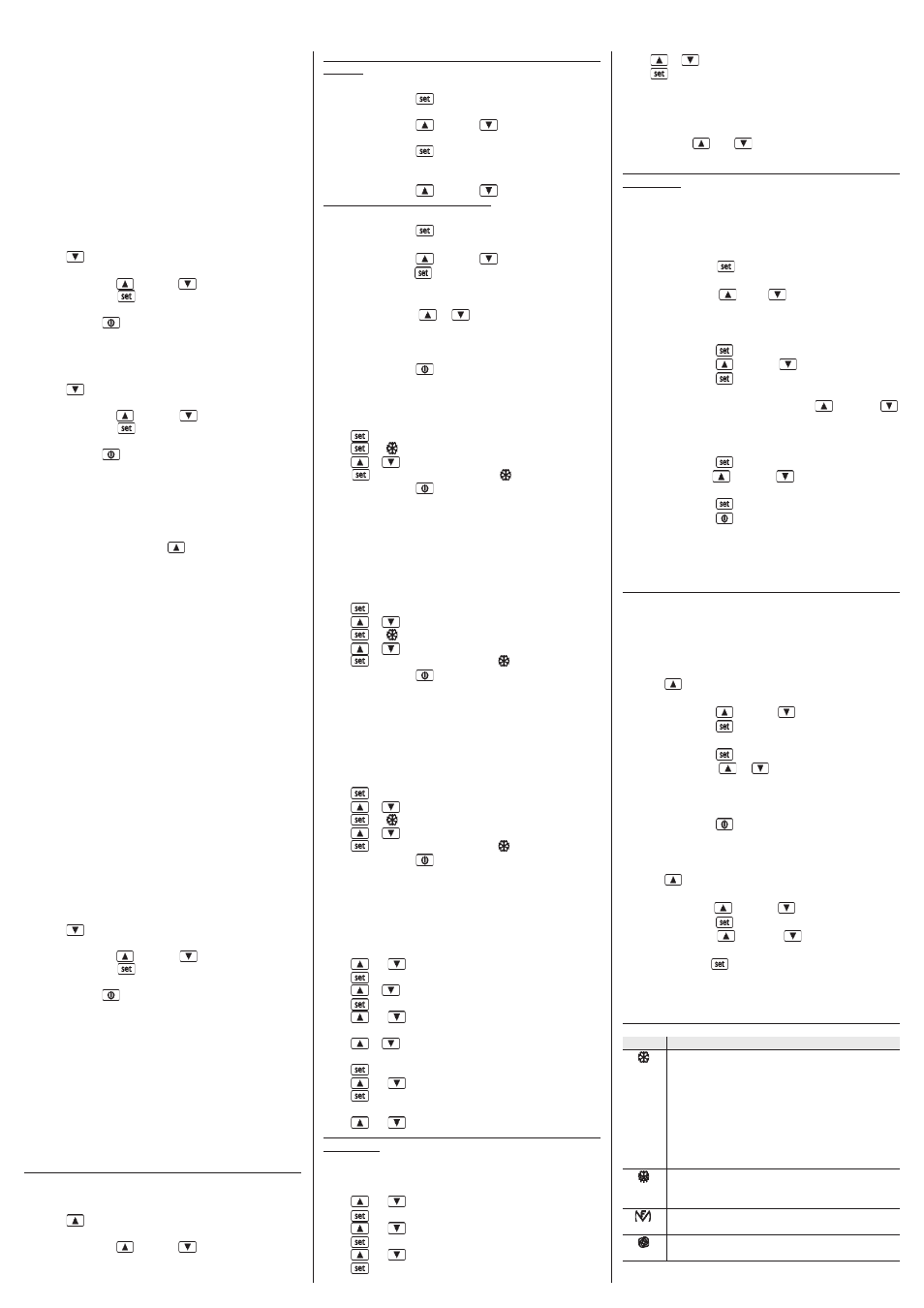
6.1 Signals
LED
MEANING
compressor LED light
if the LED is on, then the compressor is on
if the LED is flashing:
• the working set point is in the process of being changed
(via the procedure described in paragraph 4.2, 4.3 and
4.4)
• compressor protection operation in progress:
- parameters C0, C1, C2
- parameters i2 and i7
Defrost LED
If it is on:
• defrosting is in progress
Heating elements LED
if on, the heating elements will be on
Fan LED
if the LED is on, then the fan is on