EVCO EVK614N9 User Manual
Evk614
Evco S.p.A. • Code 104K614E00 • page 1/7
EVK614
Digital controller for retarder-prover cabinets and rooms, with RTC function
version 1.00
E ENGLISH
1
IMPORTANT
1.1 Important
Read these instructions carefully before installation and commission-
ing and follow the recommendations regarding installation and for
electric connection. Keep these instructions with the instrument for
future consultation.
The instrument must be disposed of in compliance with
the local Standards regarding the collection of electrical
and electronic appliances.
2
DIMENSIONS AND INSTALLATION
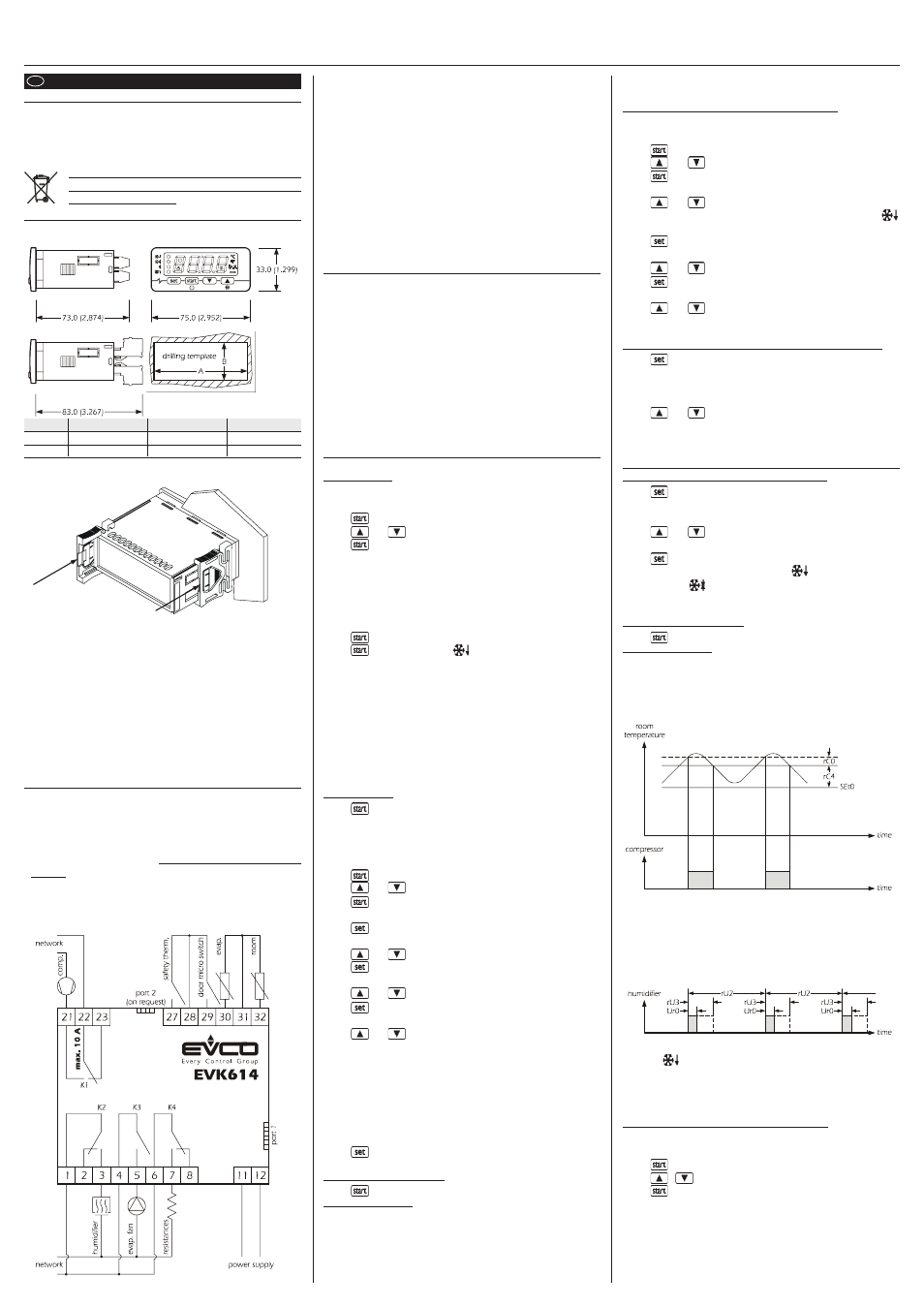
2.1 Dimensions
The dimensions are expressed in mm (in).
DIMENS.
MINIMUM
TYPICAL
MAXIMUM
A
71.0 (2.795)
71.0 (2.795)
71.8 (2.826)
B
29.0 (1.141)
29.0 (1.141)
29.8 (1.173)
2.2 Installation
Panel with click brackets supplied.
2.3 Installation recommendations
• the thickness of the panel must not exceed 8.0 mm (0.314 in)
• make sure that the work conditions (temperature of use, humidity,
etc.) lie within the limits indicated in the technical data
• do not install the instrument in vicinity of heat sources (resistances,
hot air pipes, etc.), appliances with strong magnets (large diffusers,
etc.), places subject to direct sunlight, rain, humidity, excessive dust,
mechanical vibrations or shocks
• in compliance with Safety Standards, the protection against any
contact with electric parts must be assured via correct installation of
the instrument; all parts that ensure protection must be fixed in a way
that they cannot be removed without using tools.
3
ELECTRIC CONNECTION
3.1 Preliminary considerations
With reference to the wiring diagram:
• port 1 is the serial port for communication with the supervision
system (through a serial interface, via TTL, with MODBUS communi-
cation protocol), with graphic diagram (through a serial interface)
or with the programming key; the port must be used just for one
purpose
• port 2 (on request) is the port for communication with the remote
indicator. The latter shows the temperature of the room.
3.2 Electric connection
3.3 Recommendations for the electric connection
• do not operate on terminal boards using electric or pneumatic screw-
ing devices
• if the instrument has been taken from a cold to a hot place, the
humidity could condense inside; wait about 1 hour before apply-
ing power
• make sure that the power supply voltage, the frequency and the
operational electric power of the instrument correspond with those
of the local power supply
• disconnect the power supply before proceeding with any type of
maintenance
• do not use the instrument as a safety device
• for repairs and information regarding the instrument, contact the
Evco sales network.
4
FUNCTIONING
4.1 Preliminary considerations
The following functioning cycles exist:
• automatic cycle
• heating manual cycle
• cooling manual cycle.
The automatic cycle is made up of the following phases:
- a retarding provering phase
- a storing phase
- an awakening phase
- a provering phase
- a slowing phase
On conclusion of one phase the instrument passes automatically to
the next one.
5
AUTOMATIC CYCLE
5.1 Start/stop of the automatic cycle
To start the cycle:
• make sure that the instrument is in stand-by and that there is no
procedure in progress
• press
: the display will show the first label available
• press
or
within 15 s to select “Auto”
• press
within 15 s: the display will show the following 3 times in
succession:
- the conclusion time of the provering phase (e.g. “02:00”)
- “dd” followed by the two numbers of the day of conclusion of the
provering phase (e.g. “dd26”)
- “MM” followed by the two numbers of the month of conclusion of
the provering phase (e.g. “MM03”)
• press
within 9 s: the display will show “Go”
• press
within 15 s: the LED
will switch on and the retarding-
provering phase will be started.
If the automatic cycles are not enabled (parameter P7 = 0), the “Auto”
label will not be displayed.
The end time of the provering phase is displayed in the 24 hour format
(hours:minutes). The time proposed is the same as the last automatic
cycle started but relative to the next day.
In the example, the provering phase will be concluded at 02:00 on
26 March. The display will show all information for 1 s.
If parameter P9 is set at 0, the display will only show the conclusion
time of the provering phase.
To stop the cycle:
• press
for 4 s.
5.2 Modifying the end time and date of the provering
phase
• make sure that the day and real time are set correctly, that the instru-
ment is in stand-by and that no procedure is in progress.
• press
: the display will show the first label available
• press
or
within 15 s to select “Auto”
• press
within 15 s: the display will show the end time and date
of the provering phase in succession
• press
within 9 s: the display will show “hh” followed by the
two numbers regarding the hour
• press
or
within 15 s; parameter P8 is also seen
• press
within 15 s: the display will show “nn” followed by the
two numbers regarding the minutes
• press
or
within 15 s; parameter P8 is also seen
• press
within 15 s: the display will show “dd” followed by the
two numbers regarding the day
• press
or
within 15 s; parameter P8 is also seen
- if the two numbers of the day exceed the real ones, the end date of
the provering phase will refer to the real month (e.g., if it is 26 March
and the two numbers of the day are set at 27, the end date of the
provering phase will be 27 March)
- if the two numbers of the day are lower than the real ones, the end
date of the provering phase will refer to the following month (e.g.,
if it is 26 March and the two numbers of the day are set at 25, the end
date of the provering phase will be 25 April)
• press
within 15 s: the display will show the end time and date
of the provering phase in succession again.
To go back to previous levels:
• press
during modification of the values.
To exit the procedure:
• do not operate for 15 s (any modifications will be saved).
5.3.1
Modifying the settings of the retarding-provering
phase
To set the duration of the retarding-provering phase:
• make sure that the instrument is in stand-by and that there is no
procedure in progress
• press
: the display will show the first label available
• press
or
within 15 s to select “Auto”
• press
within 15 s: the display will show the end time and date
of the provering phase in succession
• press
or
within 9 s to select “PHA1” (it is the label of the
retarding-provering phase): the LED
will switch on
• press
within 15 s: the display will show “hh” followed by the
two numbers regarding the hours
• press
or
within 15 s; parameter P8 is also seen
• press
within 15 s: the display will show “nn” followed by the
two numbers regarding the minutes
• press
or
within 15 s; parameter P8 is also seen.
It is also possible to set the duration of the retarding-provering phase
via the dur0 parameter.
To set the work set-point during the retarding-provering phase:
• press
during the modification of the duration of the retarding-
provering phase (i.e. during modification of the minutes):
the display will show “SEt” for 1 s after which the value is
shown
• press
or
within 15 s; parameters P8, rC1and rC2 are also
seen.
It is also possible to set the retarding-provering phase work set-point
via the SEt0 parameter.
To set the percentage of relative humidity during the retarding-
provering phase (only if parameter rU4 is set at 1):
• press
during the modification of the work set-point during the
retarding-provering phase: the display will show “Ur” for
1 s after which the value is shown
• press
or
within 15 s; parameters P8, rU3, rU5 and rU6
are also seen.
• press
within 15 s: the display will show “PHA2” (it is the label
of the storing phase), the LED
will switch off and the
LED
will switch on.
It is also possible to set the percentage of relative humidity during the
retarding-provering phase via the Ur0 parameter.
To go back to previous levels:
• press
during modification of the values.
To exit the procedure:
• do not operate for 15 s (any modifications will be saved).
5.3.2
The retarding provering phase
During the retarding provering phase:
• the activity of the compressor depends mainly on parameters SEt0,
rC0 and rC4
• the resistances remain off
• the evaporator fan activity depends mainly on parameter F0
• the activity of the humidifier mainly depends on parameters Ur0,
rU2 and rU3 (the rU3 parameter establishes the duration of humidi-
fier switch-on, in the course of time rU2, such to cause 100% relative
humidity). If the temperature of the room falls below that established
with parameter rU1, humidification will not be available.
• defrosting can be activated
• the LED
is on.
The retarding-provering phase has duration of the time established
via parameter dur0. When this time has expired the instrument passes
automatically to the storing phase.
5.4.1
Modifying the settings of the storing phase
To set the work set-point during the storing phase:
• make sure that the instrument is in stand-by and that there is no
procedure in progress
• press
: the display will show the first label available
• press
o
within 15 s to select “Auto”
• press
within 15 s: the display will show the end time and date
of the provering phase in succession