EVCO EV8316J9 User Manual
Ev8316
Evco S.p.A. • Code 1048316E03 • page 1/4
EV8316
Digital controller with 6 outputs for electric bread ovens, with RTC functions, programmed
switch-on and cooking timer
version 1.03
GB ENGLISH
1
IMPORTANT
1.1
Important
Read these instructions carefully before installation and use and fol-
low all recommendations regarding installation and for the electric
connection; keep these instructions for future reference.
The instrument must be disposed of according to local
Standards regarding the collection of electric and elec-
tronic appliances.
1.2
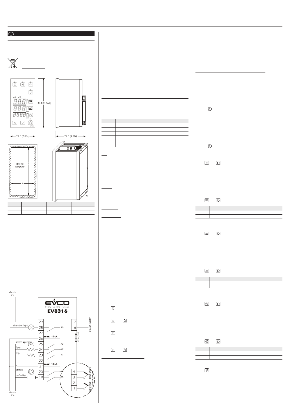
Dimensions and installation
Panel, with supplied screw bracket; dimensions in mm (in).
DIMENS.
MINIMUM
TYPICAL
MAXIMUM
A
67.0 (2.637)
67.0 (2.637)
67.8 (2.669)
B
138.0 (5.433)
138.0 (5.433)
138.8 (5.464)
Installation recommendations:
• the thickness of the panel must not exceed 10.0 mm
(0.393 in)
• position the brackets as indicated in the drawing in this paragraph;
moderate the coupling torque
• make sure that the work conditions (temperature of use, humidity,
etc.) lie within the limits indicated in the technical data
• do not install the instrument in proximity of heat sources (resistances,
hot air pipes etc.) appliances with strong magnets (large diffusers
etc.), places subject to direct sunlight, rain, humidity, excessive dust,
mechanical vibrations or shocks
• in compliance with Safety Standards, the protection against any
contact with the electric parts must be ensured via correct installa-
tion of the instrument. All parts that ensure protection must be fixed
in a way such that they cannot be removed without the aid of a tool.
1.3
Electric connection
With reference to the wiring diagram: the serial port for communica-
tion with the programming key.
Recommendations for the electric connection:
• do not operate on the terminal boards using electric or pneumatic
screwdrivers
• if the instrument has been taken from a cold place to a hot one, the
humidity could condense inside. Wait about one hour before ap-
plying power
• make sure that the power supply voltage, frequency and opera-
tional electric power correspond to those of the local power supply
• disconnect the power supply before performing any type of main-
tenance
• equip the probes with a protection able to insulate them against any
contact with metal parts or use isolated probes
• do not use the instrument as a safety device
• for repairs and information regarding the instrument, contact the
Evco sales network.
2
PRELIMINARY CONSIDERATIONS
2.1
Preliminary considerations
It is possible to set the work temperature of the top independently from
that of the floor.
The utilities managed by the digital outputs (i.e. the K1 relays... K6) are
the following:
RELAY MANAGED UTILITY
K1
top
K2
floor
K3
steam injection
K4
airhole
K5
on/stand-by
K6
chamber light
2.2
Management of the utilities
Top.
The output activity will mainly depend on the temperature of the top
(top probe), the top setpoint and the parameter r0.
Floor.
The output activity will mainly depend on the temperature of the floor
(floor probe), the floor setpoint and the parameter r6.
Steam injection.
The activity of the output depends mainly on the parameters t0, t1 and t2.
Airhole.
The output is activated in the following conditions:
• before the conclusion of the cooking timer count (the time estab-
lished with parameter c5), for the time established with parameter c6
• in manual mode, for the time established with the parameter c7.
On/Stand-by.
The output is activated during the “on” state (see paragraph 3.1).
Chamber light.
The output is activated in manual mode.
3
USER INTERFACE
3.1
Preliminary considerations
The following functioning states exist:
• “on” state (the instrument is powered and on: the regulators can be
switched on)
• “stand-by” state (the instrument is powered but switched off via soft-
ware: the regulators are off and programmed switch-on of the in-
strument is not envisioned)
• “programmed switch-on” state (the instrument is powered but
switched off via software: the regulators are off and programmed
switch-on of the instrument is envisioned)
• “off” state (the instrument is not powered).
Successively, the term “switch-on” means that the passage from the
stand-by state to the on state; the term “switch-off” means the passage
from the on state to the stand-by state.
When the instrument is powered it re-proposes the state in which it
found itself at the time when the power supply was disconnected.
3.2
Selecting the functioning state
To pass from the on state to the stand-by state (and vice versa):
• make sure that no procedure is in progress
• press
for 1s.
To pass from the on state to the programmed switch-on state:
• make sure that no procedure is in progress
• press
and
for 1s.
To pass from the programmed switch-on state to the on state:
• make sure that no procedure is in progress
• press
for 1s.
To pass from the stand-by state to the programmed switch-on state
(and vice versa):
• make sure that no procedure is in progress
• press
and
for 1s.
3.3
The display
If the instrument is in the on state:
• the highest display will show the quantity established with param-
eter P5:
- if P5 = 0, the display will show the top temperature
- if P5 = 1, the display will show the top setpoint (in this case, the
decimal point of the digit to the far right will be on)
• the central display will show the quantity established with param-
eter P6:
- if P6 = 0, the display will show the floor temperature
- if P6 = 1, the display will show the floor setpoint (in this case, the
decimal point of the digit to the far right will be on)
• the lowest display will show the quantity established with parameter P7:
- if P7 = 0, the display will show the value of the cooking timer or its
countdown if the timer is active (in this case the “timer” LED will be
on); the value of the cooking timer will be displayed in the
hour:minutes format
- if P7 = 1, the display will show the real time (in this case the “clock”
LED will be on); the real time is displayed in the 24h format
(hours:minutes).
See also paragraphs 3.5, 3.7 and 3.9
If the instrument is in the programmed switch-on state:
• the highest display will be off
• the central display will show the day of the next switch-on; the day
is visualised in 1 ... 7 format (number 1 corresponds to Monday; if
no switch-on is programmed, the central display will show “- - -”)
• the lowest display will show the time of the next switch-on; the time
is displayed in the 24h format (hours:minutes; if no switch-on is
programmed, the lowest display will show “- - - -”)
• the “delay” LED will be on
• the LED will be on.
If the instrument is in the stand-by state:
• the highest display will be off
• the central display and the lowest one:
- will be off if parameter c8 is set at 0
- they will respectively show the day of the week and the real time if
the parameter c8 is set at 1 (in this case the “clock” LED will be on);
the day is displayed in the 1 ... 7 format (number 1 corresponds to
Monday), the real time in the 24 hour format (hours:minutes)
• the LED will be on.
3.4
Temporary setting of the quantity shown on the
highest display during the on state
• make sure that no procedure is in progress
• press
and
for 1s several times. the highest display will show
one of the labels stated in the tables in paragraph
3.5 for 2s, after which it will show the corre-
sponding value.
A power cut causes the restore of the display of the quantity estab-
lished with parameter P5.
3.5
Learning of the quantity shown on the highest
display during the on state
• make sure that no procedure is in progress
• press
and
: the highest display will show one of the labels
reported in the following table for 2s:
LABEL MEANING
Pb1
temperature of the top
SP1
top setpoint
3.6
Temporary setting of the quantity shown on the
central display during the on state
• make sure that no procedure is in progress
• press
and
for 1s several times. the central display will show
one of the labels stated in the tables in paragraph
3.7 for 2s, after which it will show the corre-
sponding value.
A power cut causes the restore of the display of the quantity estab-
lished with parameter P6.
3.7
Learning of the quantity shown on the central
display during the on state
• make sure that no procedure is in progress
• press
and
: the central display will show one of the labels
given in the following table for 2s:
LABEL MEANING
Pb2
temperature of the floor
SP2
floor setpoint
3.8
Temporary setting of the quantity shown on the
lowest display during the on state
• make sure that no procedure is in progress
• press
and
for 1s several times. the lowest display will show
one of the labels stated in the tables in paragraph
3.9 for 2s, after which it will show the corre-
sponding value.
A power cut causes the restore of the display of the quantity estab-
lished with parameter P7.
3.9
Learning of the quantity shown on the lowest
display during the on state
• make sure that no procedure is in progress
• press
and
: the lowest display will show one of the labels
reported in the following table for 2s:
LABEL MEANING
tine
cooking timer value or count if the timer is activated
rtc
real time
3.10 Chamber light switch-on/off
• make sure that no procedure is in progress
• press
3.11 Buzzer silencing
• make sure that no procedure is in progress
• press a key (the first time the key is pressed does not cause the asso-
ciated effect).