EVCO EK342AJ7 User Manual
Page 2
(5)
the outputs are turned ON as much as possible alternatively.
6
CONFIGURATION PARAMETERS
6.1
How to set configuration parameters
Configuration parameters are arranged on two levels.
To gain access the first level:
• press
and
for 4 s
: the instrument
will show
To select a parameter:
• press
or
To modify the value of the parameter:
• press
and
or
To gain access the second level:
• gain access the first level
• press
or
to select
• press
and
or
to select “ -19 “
• press
and
for 4 s
: the instrument
will show
To quit the procedure:
• press
and
for 4 s
or do not oper-
ate for about 60 s.
7
SIGNALS
7.1
Signals
the buzzer will be activated for the time you have set with param-
eter c4.
(2)
you can set the cooking timer between 1 and 99 min.
4
WORKING SETPOINT
4.1
How to set the working setpoint
• press
• press
or
within 4 s
(3)
• press
(3)
you can set the working setpoint between the limits you have set with param-
eters rA1 and rA2.
5
PERCENTAGE OF POWER SUPPLIED TO THE HEAT-
ING GROUPS
5.1
How to set the percentage of power supplied to
the heating groups
To modify the value of the percentage of power supplied to the
top heating group:
• press
• press
or
within 4 s
(4)
• press
The time the top output is turned ON is “ {[(time you have set
with parameter c1) / 10} x (number of bars turned ON in the LED
bar at the top) “
(5)
.
To modify the value of the percentage of power supplied to the
floor heating group:
• press
during the modification of
the percentage of power
supplied to the top heat-
ing group
• press
or
within 4 s
(4)
• press
The time the floor output is turned ON is “ {[(time you have set
with parameter c1) / 10} x (number of bars turned ON in the LED
bar at the bottom) “
(5)
.
(4)
if parameter c0 has value 1, the modification of the percentage of power
supplied to a heating group will automatically provoke the supply of the maxi-
mum power to the other one and vice versa; if parameter c0 has value 2, the
modification of the percentage of power supplied to a heating group will auto-
matically provoke an adjustment of the other one such as to guarantee that the
sum of bars turned ON will always be 10
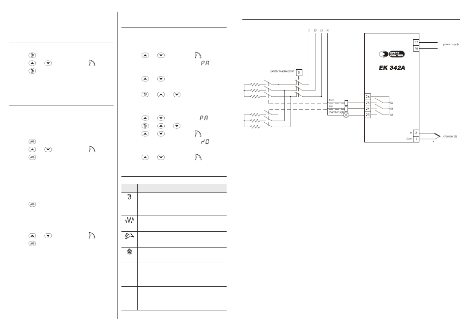
11
ELECTRICAL CONNECTION
11.1 Electrical connection
(8)
provide the probe with a protection able to protect it against contacts with metal parts or use insulated probes.
LED
°
C
°
F
MEANING
LED regulator
if it is lit, the temperature the chamber probe is reading is below the
working setpoint
LED top and floor
if they are lit, the top output and the floor output will be turned ON
LED quick heating
if it is lit, function Quick heating will be activated
LED chamber light
if it is lit, the chamber light will be lit
LED Celsius degree
if it is lit, the unit of measure of the temperature showed by the instru-
ment will be Celsius degree
LED Fahrenheit degree
if it is lit, the unit of measure of the temperature showed by the instru-
ment will be Fahrenheit degree