EVCO EK340AJ7 User Manual
Page 3
Every Contr
ol S.r
.l. • EK 340A • Sheet 2/2
The indications showed by the instrument flashes, except the indications “AL1“ and
“AL2“ (they are alternated with the temperature the chamber probe is reading) and
the buzzer utters an intermittent beep.
8
TECHNICAL DATA
8.1
Technical data
Box: self-extinguishing grey.
Size: 72 x 144 x 79 mm (2.83 x 5.66 x 3.11 in).
Installation: panel mounting, panel cut out 67 x 138 mm (2.63 x 5.43 in), with screw
brackets (supplied by the builder).
Frontal protection: IP 54.
Connections: extractable terminal blocks with pitch 7.5 mm (0.29 in) for cables up
to 2.5 mm² (0.38 sq in, power supply and outputs) and with pitch 5 mm (0.19 in) for
cables up to 2.5 mm² (0.38 sq in, input).
Ambient temperature: from 0 to 55 °C (32 to 131 °F, 10 ... 90% of relative humidity
without condensate).
Power supply: 230 Vac, 50/60 Hz, 4 VA (standard) or 115 Vac, 50/60 Hz, 4 VA
(by request).
Alarm buzzer: included.
Measure inputs: 1 (chamber probe) for “J” or “K” thermocouples.
Working range: from 0 to 700 °C (32 to 999 °F) for “J” thermocouple,
from 0 to 999 °C (32 to 999 °F) for “K” thermocouple.
Setpoint range: from 0 to 999 °C (0 to 999 °F).
Resolution: 1 °F with unit of measure in Fahrenheit, 1 °C with unit of measure in
Celsius.
Display: one red LED 3-digit displays 13.2 mm (0.51 in) high, two LED bars (10 red
LED), output status indicators, indicators of the unit of measure of the temperature
showed by the instrument.
Outputs: 3 relays: one 8 A @ 250 Vac relay for top heating group control (NO),
one 8 A @ 250 Vac relay for floor heating group control (NO), one 8 A @ 250 Vac relay
for chamber light control (NO); the maximum current allowed on terminal 26 is 10 A.
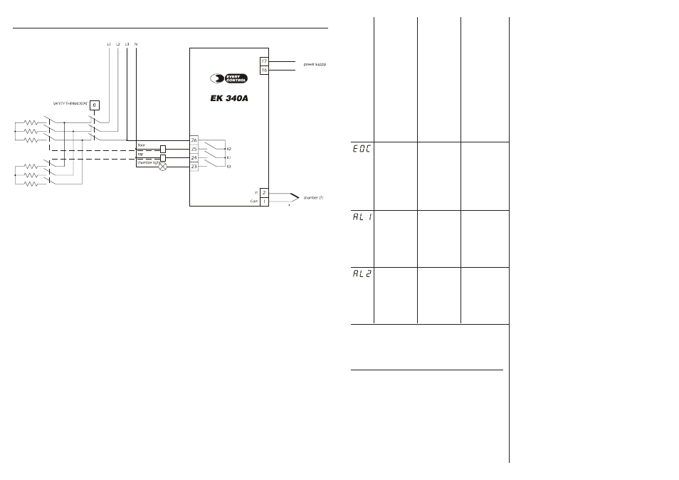
cold joint
alarm
first
tempera-
ture
alarm
second
tempera-
ture
alarm
• the chamber probe
plays up
• the connection in-
strument-chamber
probe is wrong
• the temperature the
chamber probe is
reading is outside
the limits allowed by
the working range
of the instrument
there is a defect in the
cold joint of the instru-
ment
the temperature the
chamber probe is
reading is outside the
limit you have set with
parameter AA1
the temperature the
chamber probe is
reading is outside the
limit you have set with
parameter Ab1
• test connection in-
strument-probe
• test the tempera-
ture close to the
probe
turn OFF the power
supply of the instru-
ment: unless the alarm
disappears, you will
have to change the
instrument
test the temperature
close to the probe (look
at parameters AA0,
AA1 and AA4)
test the temperature
close to the probe (look
at parameters Ab0,
Ab1 and Ab4)
• the top output will be
turned OFF
• the floor output will be
turned OFF
no effect
no effect
10
ELECTRICAL CONNECTION
10.1 Electrical connection
(7)
provide the probe with a protection able to protect it against contacts with metal parts or use insulated probes.