EVCO EVRSF205N9VRB User Manual
Page 5
EVCO S.p.A. | Codice 104RSF200E124 | Page 5 of 8 | PT 20/14 | version 1.1
14
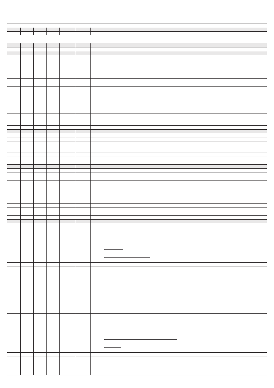
WORKING SETPOINT AND CONFIGURATION PARAMETERS
14.1
Working set-point
PARAM.
MIN.
MAX.
U.M.
EVRSF204 EVRSF205 WORKING SETPOINT
r1
r2
°C/°F (1)
-18,0
-18,0
working set-point; see also r0
14.2
Configuration parameters
PARAM.
MIN.
MAX.
U.M.
EVRSF204 EVRSF205 WORKING SETPOINT
SP
r1
r2
°C/°F (1)
-18,0
-18,0
working set-point; see also r0
PARAM.
MIN.
MAX.
U.M.
EVRSF204 EVRSF205 MEASUREMENT INPUTS
CA1
-25
25,0 °C/°F (1)
0,0
0,0
offset cell probe
CA2
-25
25,0 °C/°F (1)
0,0
0,0
offset evaporator probe
CA3
-25
25,0 °C/°F (1)
0,0
0,0
offset condenser probe
P0
0
1
- - -
1
1
probe type
0
=
PTC
1
=
NTC
P1
0
1
- - -
1
1
degree Celsius decimal point (during normal operation)
1
=
YES
P2
0
1
- - -
0
0
temperature unit of measurement (2)
0
=
°C
1
=
°F
P3
0
2
- - -
1
1
evaporator probe function
0
=
probe absent
1
=
defrosting probe and probe for evaporator fan thermostating
2
=
probe for evaporator fan thermosatating
P4
0
1
- - -
1
1
third input function
0
=
digital input (micro switch/multi-function input 1)
1
=
analogue input (condenser probe)
P8
0
250
0.1 s
5
5
delay displaying temperature variation detected by the probes
PARAM.
MIN.
MAX.
U.M.
EVRSF204 EVRSF205 MAIN REGULATOR
r0
0,1 (3)
15,0 °C/°F (1)
2,0
2,0
working set-point differential
r1
-99
r2
°C/°F (1)
-50
-50
minimum working set-point
r2
r1
99,0 °C/°F (1)
50,0
50,0
maximum working set-point
r3
0
1
- - -
0
0
locking of working set-point calibration (using the procedure described in paragraph 10.1)
1
=
YES
r4
0,0
99,0 °C/°F (1)
0,0
0,0
increase in temperature during “energy saving” function; see also i0, i5 and i10
r5
0,0
99,0 °C/°F (1)
0,0
0,0
decrease in temperature during “overcooling” function; see also r6
r6
0
240
min
30
30
duration of “overcooling” function; see also r5
PARAM.
MIN.
MAX.
U.M.
EVRSF204 EVRSF205 COMPRESSROR PROTECTION SYSTEM
C0
0
240
min
0
0
delay in switching on of compressor after the device switches on (4)
C1
0
240
min
5
5
minimum time between two consecutive compressor start-ups; also delay in compressor start-up after conclusion of cell probe
error (code “Pr1”) (5) (6)
C2
0
240
min
3
3
minimum compressor switch-off duration; see also C18 (5) (7)
C3
0
240
s
0
0
minimum duration of compressor switch on time
C4
0
240
min
10
10
duration of compressor switch off during cell probe error (code “Pr1”); see also C5
C5
0
240
min
10
10
duration of compressor switch on during cell probe error (code “Pr1”); see also C4
C6
0,0
199
°C/°F (1)
80,0
80,0
condenser temperature is higher than that at which the condenser overheating alarm is activated (code “COH”) (8)
C7
0,0
199
°C/°F (1)
90,0
90,0
condenser temperature above which the blocked compressor alarm is activated (“CSd” code)
C8
0
15
min
1
1
blocked compressor alarm delay (“CSd” code) (9)
C10
0
999
10 h
0
0
number of operating hours is higher than the limit at which the need for maintenance is signalled.
0
=
function absent
C11
0
240
s
3
3
compressor 2 switch-on delay from compressor 1 switch-on (only if u1 and/or u11 = 7) (10)
PARAM.
MIN.
MAX.
U.M.
EVRSF204 EVRSF205 DEFROSTING
d0
0
99
h
8
8
if d8 = 0, 1 or 2, defrosting interval (11)
0
=
interval defrosting will never be activated
if d8 = 3, maximum defrost interval
d1
0
2
- - -
0
0
type of defrosting
0
=
ELECTRIC - during defrosting the compressor will remain off and the defrosting output will be activated; evaporator fan
activity will depend on parameter F2
1
=
BY HOT GAS - during defrosting the compressor will be switched on and the defrosting output will be activated;
evaporator fan activity will depend on parameter F2
2
=
VIA STOPPING OF COMPRESSOR - during defrosting the compressor will remain switched off and the defrosting output
will remain deactivated; evaporator fan activity will depend on parameter F2
d2
-99
99,0 °C/°F (1)
2,0
2,0
temperature at end of defrosting (only if P3 = 1); see also d3
d3
0
99
min
30
30
se P3 = 0 or 2, defrosting duration
se P3 = 1, maximum defrosting duration; see also d2
0
=
defrosting will not be activated
d4
0
1
- - -
0
0
defrosting on device switch-on (4)
1
=
YES
d5
0
99
min
0
0
if d4 = 0, minimum time between switching on of device and activation of defrosting; see also i0 and i5 (4)
if d4 = 1, delay in activation of defrosting after device is switched on ; see also i0 and i5 (4)
d6
0
1
- - -
1
1
temperature displayed during defrosting
0
=
cell temperature
1
=
if at the time of defrosting activation, the cell temperature is lower than the “working set-point + r0”, at most “working
set- point + r0”; if at the time of defrosting activation, the cell temperature is higher than the “working set-point + r0”,
at most the cell temperature when defrosting is activated (12)
d7
0
15
min
2
2
dripping duration (during dripping the compressor will remain switched off and the defrosting output will remain deactivated; if
d16 = 0, evaporator fan activity will depend on parameter F2; if d16 ≠ 0, the evaporator fan will remain switched off)
d8
0
3
- - -
0
0
defrosting activation methods
0
=
AT INTERVALS - defrosting will be activated once the device has altogether been running for time d0
1
=
AT INTERVALS - FOR COMPRESSOR SWITCH-ON - defrosting will be activated once the compressor has altogether been
switched on for time d0
2
=
AT INTERVALS - FOR EVAPORATOR TEMPERATUREE - defrosting will be activated when the evaporator temperature
has remained below the temperature d9 for a total time of d0 (13)
3
=
ADAPTABLE - defrosting will be activated at intervals, whose duration will each time depend on the duration of
compressor switch-ons and the evaporator temperature; see also d18, d19 and d22 (13)
d9
-99
99,0 °C/°F (1)
0,0
0,0
evaporator temperature is higher than that at which the defrost interval counter is suspended (only if d8 = 2)
d11
0
1
- - -
0
0
defrosting alarm switches off once maximum time limit has been reached (code “dFd”; only if P3 = 1 and in absence of an
evaporator probe (code “Pr2”)
1
=
YES
d15
0
99
min
0
0
minimum time that the compressor must be switched on before defrosting can be activated (only if
d1 = 1) (14)