6 memory, 7 input/output ports, Table 7-1: 2x20 gpio pin-out to fpga pins – Digilent 6005-210-000 User Manual
Page 6
6 Memory
The Opus has a total of 256 MB of DDR-2 RAM, divided into two banks of 128 MB. Each bank is organized into 32 bit
words, which can be written and read in bursts by enabling burst mode. In big endian format, writing a 1 to the 31
st
bit of the configuration register enables burst mode. The configuration register for each bank is located at the base
address of the registers.
The Opus card also has 32 Mb of platform flash, which can store hardware bitstreams between power cycles. The
platform flash can be programmed with the Xilinx iMPACT tool, by selecting the XCF32P in the device chain. The card
can be configured to automatically load from the platform flash at power on or reset by using jumper blocks on the
MODE 0 and MODE 1 pin pairs on the Mode jumper, located at J13.
7 Input/Output Ports
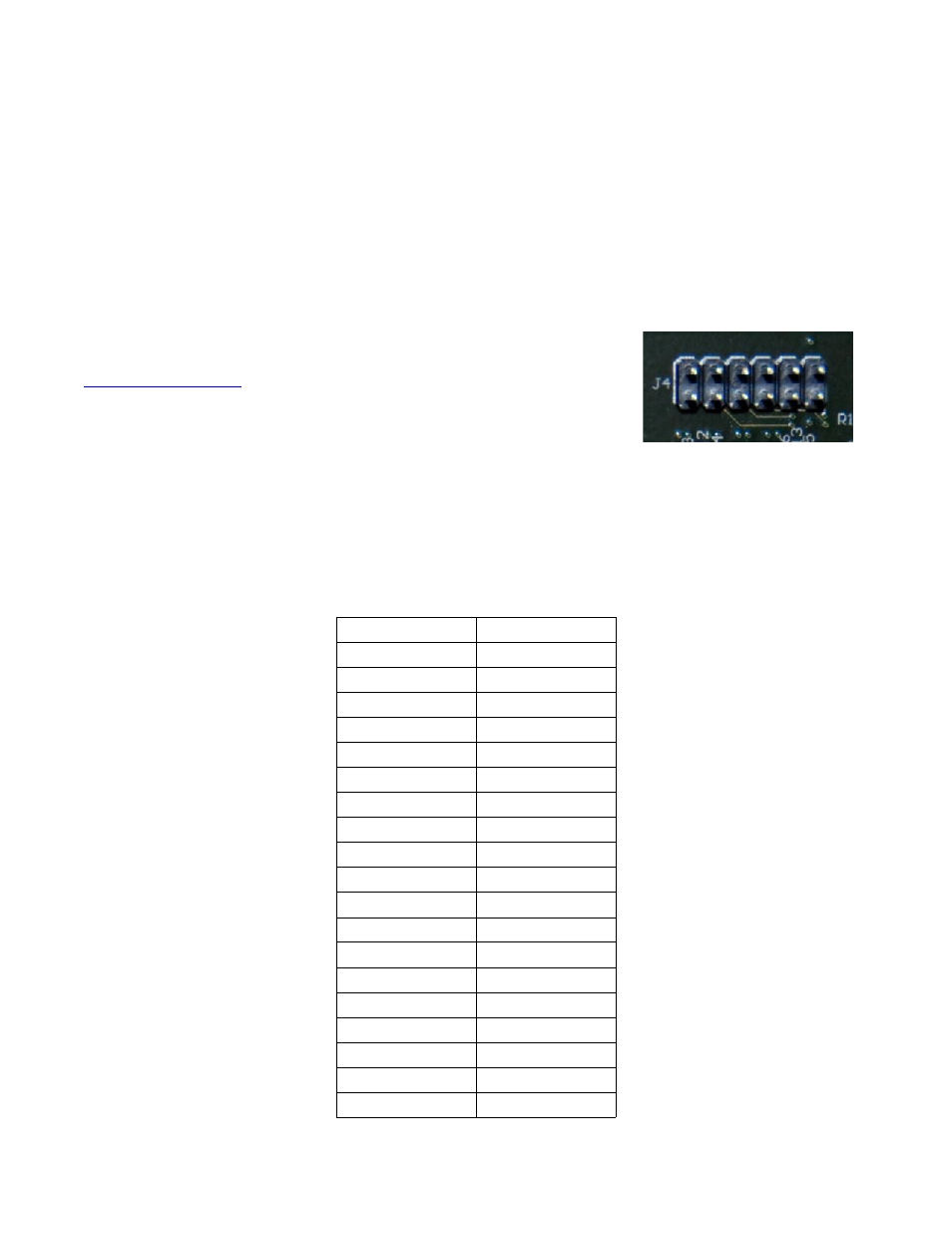
The Opus card has two serial RS232 Pmods, located at J11. Using Digilent's
which uses one of the RS232 Pmods, the pins can be
used to connect to a host PC and communicate with a terminal emulator. This
communication point presents a wide variety of uses, such as debugging designs,
software application I/O, and more. For the included Linux system, ensure the
RS-232 Pmod cable connects from pin 1 on J4 to pin 1 on the RS232 Pmod to
provide the Linux system console. The port configuration should be set to 115,200 baud, 8-bits, no parity, one stop bit,
and software flow control.
The Opus card also has a 2x20 general purpose I/O port, with pins that can be configured as input or output based on
hardware configuration settings. The GPIO pin-out is listed in Table 7-1:
Table 7-1: 2x20 GPIO Pin-out to FPGA Pins
Pin 1: GND
Pin 2: VU12V0
Pin 3: VCC3V3
Pin 4: C12
Pin 5: C11
Pin 6: D11
Pin 7: D10
Pin 8: C9
Pin 9: D9
Pin 10: G9
Pin 11: F8
Pin 12: F9
Pin 13: E8
Pin 14: F7
Pin 15: C7
Pin 16: G7
Pin 17: A12
Pin 18: B12
Pin 19: B11
Pin 20: A10
Pin 21: B10
Pin 22: A9
Pin 23: B9
Pin 24: A8
Pin 25: A7
Pin 26: B7
Pin 27: B6
Pin 28: A5
Pin 29: B5
Pin 30: A4
Pin 31: B4
Pin 32: A3
Pin 33: C8
Pin 34: D8
Pin 35: E7
Pin 36: C6
Pin 37: D6
Pin 38: E6
Pin 39: E5
Pin 40: D5
Reference Manual
©
2010 Computer Measurement Laboratory
6 of 7