Display surface – Digilent Basys Board Rev.E User Manual
Page 9
Digilent
Basys Reference Manual
www.digilentinc.com
Copyright Digilent, Inc.
Page 9/12
Doc: 502-107
larger electrostatic force that results from the entire phosphor-coated display surface of the CRT being
charged to 20kV (or more). The rays are focused to a fine beam as they pass through the center of
the grids, and then they accelerate to impact on the phosphor-coated display surface. The phosphor
surface glows brightly at the impact point, and it continues to glow for several hundred microseconds
after the beam is removed. The larger the current fed into the cathode, the brighter the phosphor will
glow.
Between the grid and the display surface, the beam passes through the neck of the CRT where two
coils of wire produce orthogonal electromagnetic fields. Because cathode rays are composed of
charged particles (electrons), they can be deflected by these magnetic fields. Current waveforms are
passed through the coils to produce magnetic fields that interact with the cathode rays and cause
them to transverse the display surface in a “raster” pattern, horizontally from left to right and vertically
from top to bottom. As the cathode ray moves over the surface of the display, the current sent to the
electron guns can be increased or decreased to change the brightness of the display at the cathode
ray impact point.
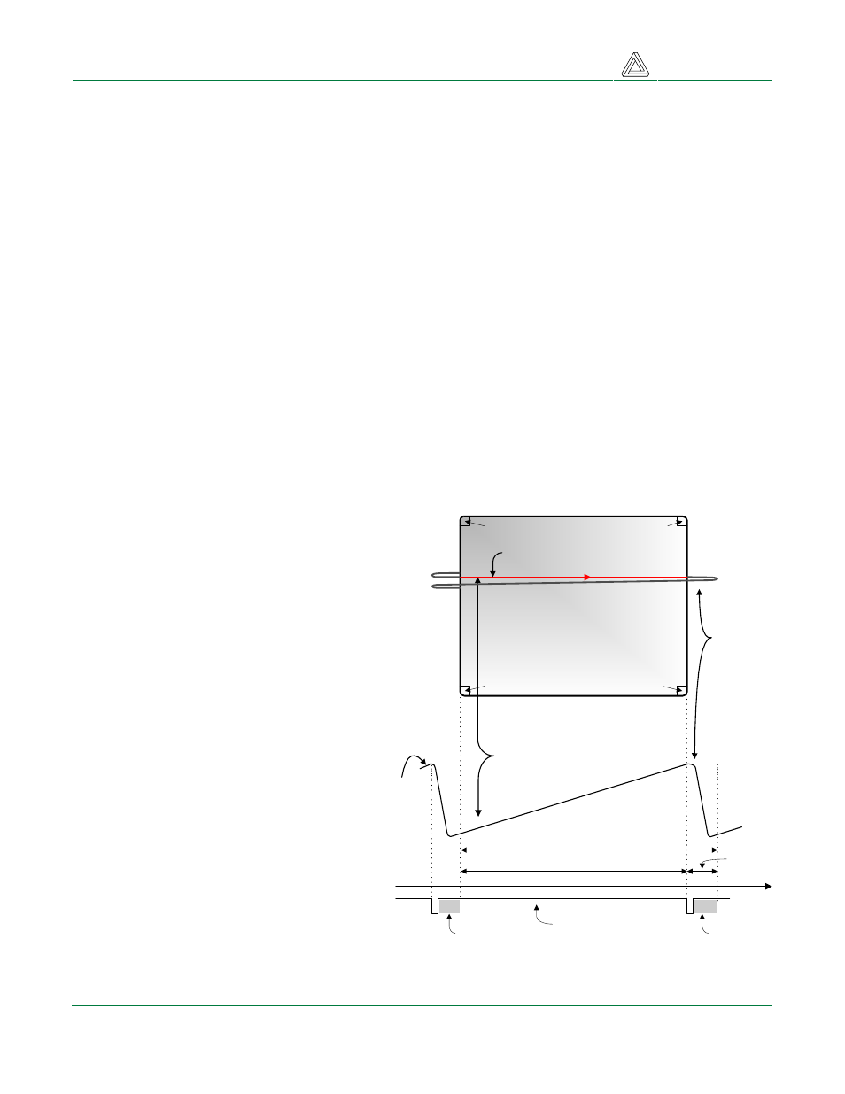
Information is only displayed when the beam is moving in the “forward” direction (left to right and top
to bottom), and not during the time the beam is reset back to the left or top edge of the display. Much
of the potential display time is therefore lost in “blanking” periods when the beam is reset and
stabilized to begin a new horizontal or vertical display pass. The size of the beams, the frequency at
which the beam can be traced across the display, and the frequency at which the electron beam can
be modulated determine the display resolution. Modern VGA displays can accommodate different
resolutions, and a VGA controller
circuit dictates the resolution by
producing timing signals to control the
raster patterns. The controller must
produce synchronizing pulses at 3.3V
(or 5V) to set the frequency at which
current flows through the deflection
coils, and it must ensure that video
data is applied to the electron guns at
the correct time. Raster video displays
define a number of “rows” that
corresponds to the number of
horizontal passes the cathode makes
over the display area, and a number of
“columns” that corresponds to an area
on each row that is assigned to one
“picture element” or pixel. Typical
displays use from 240 to 1200 rows
and from 320 to 1600 columns. The
overall size of a display and the
number of rows and columns
determines the size of each pixel.
Video data typically comes from a
video refresh memory, with one or
more bytes assigned to each pixel
location (the Basys uses three bits per
pixel). The controller must index into
video memory as the beams move
Current
waveform
through
horizontal
defletion
coil
Stable current ramp - information
is displayed during this time
Retrace - no
information
displayed
during this
time
Total horizontal time
Horizontal display time
Horizontal sync signal
sets retrace frequency
retrace
time
time
HS
"back porch"
"front porch"
Display Surface
640 pixels per row are displayed
during forward beam trace
pixel 0,639
pixel 0,0
pixel 479,0
pixel 479,639
Figure 15. VGA system signals