Digilent Basys Board Rev.E User Manual
Page 11
Digilent
Basys Reference Manual
www.digilentinc.com
Copyright Digilent, Inc.
Page 11/12
Doc: 502-107
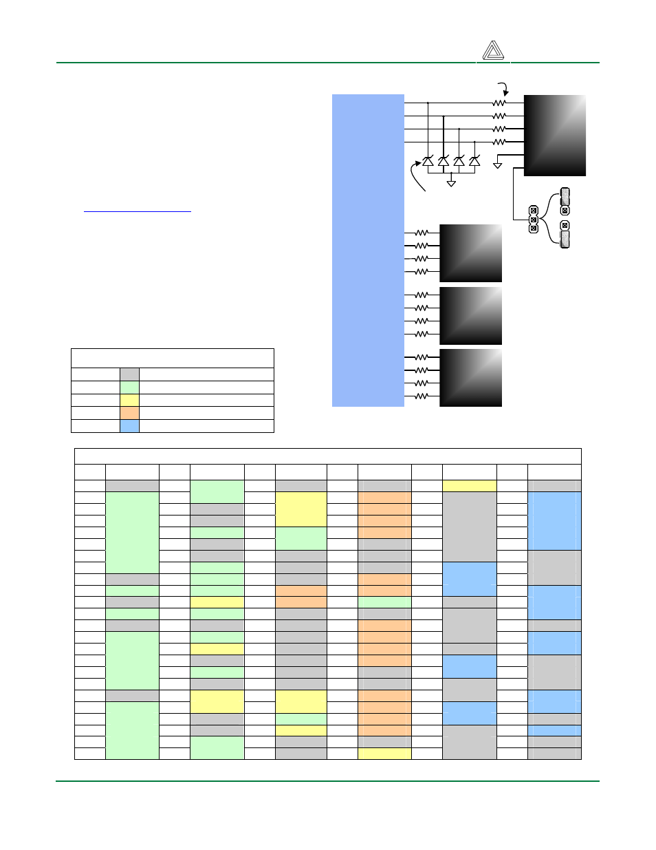
Expansion Connectors (6-pin headers)
The Basys board provides four 6-pin peripheral
module connectors. Each connector provides
Vdd, GND, and four unique FPGA signals.
Several 6-pin module boards that can attach to
this connector are available from Digilent,
including A/D converters, speaker amplifiers,
microphones, H-bridge amplifiers, etc. Please
see
www.digilentinc.com
for more information.
FPGA Pin Definitions
The table below shows all pin definitions for the
Spartan-3E on the Basys board. Pins in grey
boxes are not available to the user
FPGA pin definition table color key
Grey
Not available to user
Green
User I/O devices
Yellow
Data ports
Tan
Pmod connector signals
Blue
USB signals
Basys Spartan-3E pin definitions
Pin
Signal
Pin
Signal
Pin Signal Pin
Signal
Pin
Signal
Pin
Signal
1
PROG
25
CA
49
VDDO-2
73
GND
97
PS2D
121
VDDO-0
2
LD7
26
AN3
50
GRN2
74
JD-3
98
NC
122
U-INT0
3
LD6
27
GND
51
GRN1
75
JD-1
99
GND
123
U-FLAGC
4
LD5
28
VDDO-3
52
GRN0
76
JC-3
100
VDDO-1
124
U-FLAGB
5
LD4
29
SW2
53
CLK2
77
JC-1
101
NC
125
U-FLAGA
6
SW7
30
VDDAUX
54
CLK1
78
NC
102
VDDAUX
126
U-IFCLK
7
LD3
31
NC
55
GND
79
VDDO-1
103
NC
127
GND
8
LD2
32
AN2
56
NC
80
VDDINT
104
U-SLWR
128
NC
9
VDDINT
33
AN1
57
MODE2
81
JA-1
105
U-SLRD
129
NC
10
SW6
34
AN0
58
JD-4
82
JA-3
106
U-SLCS
130
U-D7
11
GND
35
VS
59
JD-2
83
CG
107
NC
131
U-D6
12
SW5
36
SW1
60
MODE1
84
NC
108
TMS
132
U-D5
13
VDDO-3
37
GND
61
GND
85
JC-4
109
TDO
133
GND
14
LD1
38
SW0
62
MODE0
86
JC-2
110
TCK
134
U-D4
15
LD0
39
HS
63
DIN
87
JB-1
111
NC
135
U-D3
16
CB
40
INIT
64
VDDO-2
88
JB-3
112
U-PKTD
136
NC
17
CF
41
BTN3
65
VDDAUX
89
NC
113
U-FAD1
137
VDDAUX
18
SW4
42
VDDO-2
66
NC
90
GND
114
NC
138
VDDO-0
19
GND
43
BLUE1
67
RED2
91
JA-2
115
VDDINT
139
U-D2
20
CE
44
BLUE0
68
RED1
92
JA-4
116
U-FAD0
140
U-D1
21
CD
45
VDDINT
69
BTN0
93
JB-2
117
U-SLDE
141
NC
22
DP
46
GND
70
RED0
94
JB-4
118
GND
142
U-D0
23
CC
47
BTN2
71
CCLK
95
NC
119
NC
143
HSWAP
24
SW3
48
BTN1
72
DONE
96
PS2C
120
NC
144
TDI
Spartan 3E
FPGA
81
91
82
92
ESD protection
diodes
1
6-pin
header
2
3
4
5
6
JA
Short-circuit protection
resistors
VU
3.3V
JPA
Power
supply
jumper
1
6-pin
header
2
3
4
JB
1
6-pin
header
2
3
4
JC
1
6-pin
header
2
3
4
JD
87
93
88
94
77
86
76
85
75
59
74
58
Note
Every 6-pin
connector has a
power supply
jumper and ESD
diodes, although
they are only
shown for JPA.
Figure 18. Basys Pmod connector circuits