Digilent Basys Board Rev.E User Manual
Page 3
Digilent
Basys Reference Manual
www.digilentinc.com
Copyright Digilent, Inc.
Page 3/12
Doc: 502-107
power-cycle event or by the FPGA reset
button (BTNR) being pressed. The Platform
Flash ROM will retain a bit file until it is
reprogrammed, regardless of power-cycle
events.
To program the Basys board, attach the USB
cable to the board (if USB power will not be
used, attach a suitable power supply to the
power jack or battery connector on the board,
and set the power switch to VEXT). Start the
Adept software, and wait for the FPGA and
the Platform Flash ROM to be recognized.
Use the browse function to associate the
desired .bit file with the FPGA, and/or the
desired .mcs file with the Platform Flash
ROM. Right-click on the device to be
programmed, and select the “program”
function. The configuration file will be sent to the FPGA or Platform Flash, and the software will
indicate whether programming was successful. The “configuration done” LED (LD_D) will also
illuminate after the FPGA has been successfully configured. For further information on using Adept,
please see the Adept documentation available at the Digilent website.
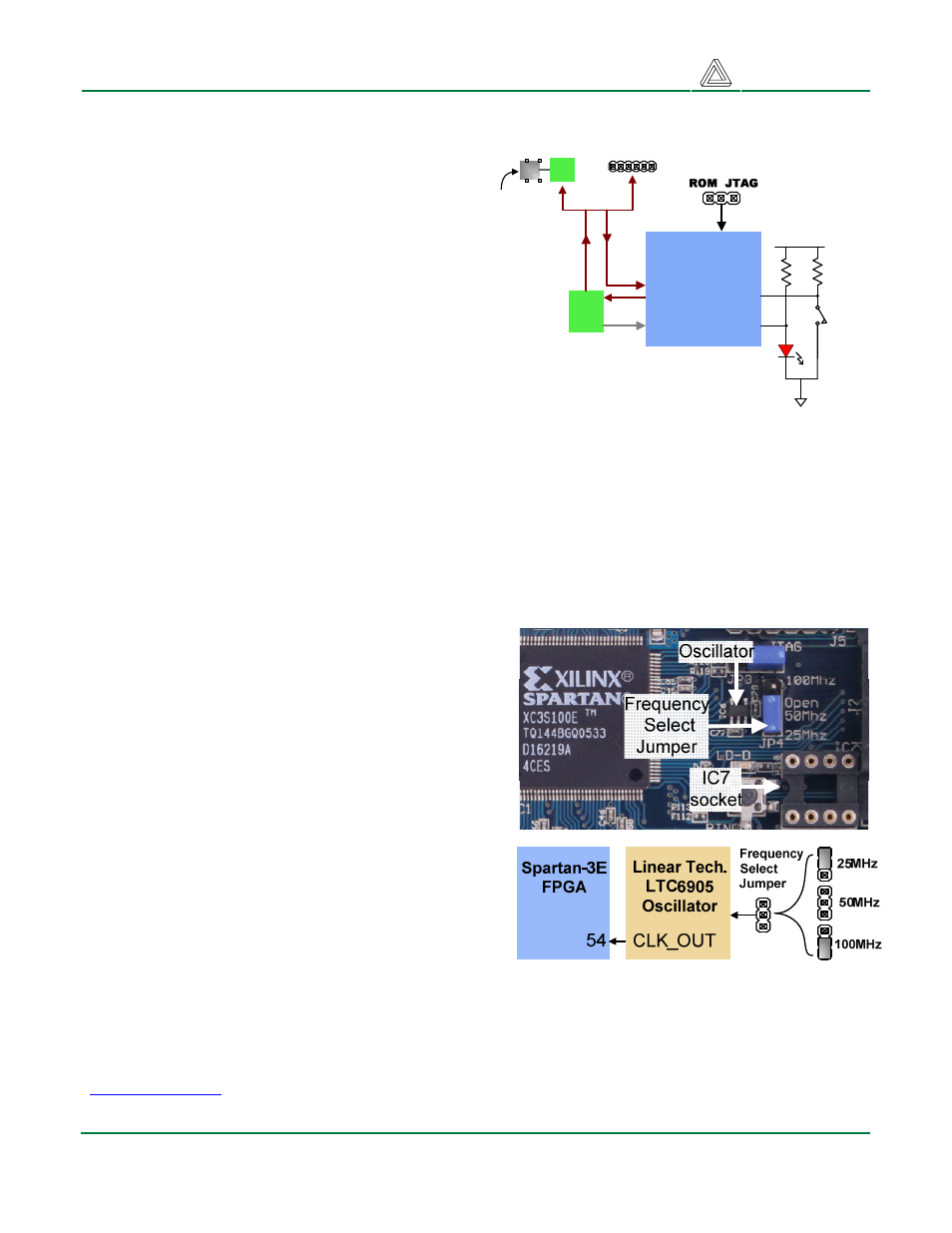
Oscillators
The Basys board includes a primary, user-
settable silicon oscillator that produces 25MHz,
50MHz, or 100MHz based on the position of the
clock select jumper at JP4. A socket for a second
oscillator is provided at IC7 (the IC7 socket can
accommodate any 3.3V CMOS oscillator in a
half-size DIP package).
The primary and
secondary oscillators are connected to global
clock input pins at pin 54 and pin 53 respectively.
Both clock inputs can drive the clock synthesizer
DLL on the Spartan 3E, allowing for a wide range
if internal frequencies, from 4 times the input
frequency to any integer divisor of the input
frequency.
The primary silicon oscillator is flexible and
inexpensive, but it lacks the frequency stability of
a crystal oscillator. Some circuits that drive a
VGA monitor may realize a slight improvement in
image stability by using a crystal oscillator
installed in the IC7 socket. For these applications, a 25MHz (or 50MHz) crystal oscillator, available
from any catalog distributor, is recommended (see for example part number SG-8002JF-PCC at
www.digikey.com
).
Figure 5. Basys oscillator circuits
XCF02
Platform
Flash
JTAG
header
JTAG
PROG
DONE
Vdd
Done
LED
(LD-D)
FPGA
Reset
Button
(BTNR)
Spartan 3E
FPGA
Mode
Jumper
USB miniB
connector
Cypress
EZ-USB
Slave
serial
port
JTAG
port
Figure 4. Basys Programming Circuits