Digilent Basys Board Rev.E User Manual
Page 5
Digilent
Basys Reference Manual
www.digilentinc.com
Copyright Digilent, Inc.
Page 5/12
Doc: 502-107
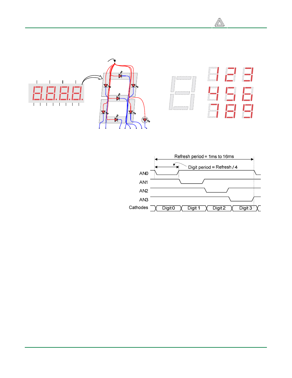
illuminated just one-quarter of the time, but because the eye cannot perceive the darkening of a digit
before it is illuminated again, the digit appears continuously illuminated. If the update or “refresh” rate
is slowed to a given point (around 45 hertz), then most people will begin to see the display flicker.
For each of the four digits to appear
bright and continuously illuminated, all
four digits should be driven once every 1
to 16ms (for a refresh frequency of
1KHz to 60Hz). For example, in a 60Hz
refresh scheme, the entire display would
be refreshed once every 16ms, and
each digit would be illuminated for ¼ of
the refresh cycle, or 4ms. The controller
must assure that the correct cathode
pattern is present when the
corresponding anode signal is driven.
To illustrate the process, if AN1 is
asserted while CB and CC are asserted, then a “1” will be displayed in digit position 1. Then, if AN2 is
asserted while CA, CB and CC are asserted, then a “7” will be displayed in digit position 2. If A1 and
CB, CC are driven for 4ms, and then A2 and CA, CB, CC are driven for 4ms in an endless
succession, the display will show “17” in the first two digits. Figure 8 shows an example timing
diagram for a four-digit seven-segment controller.
PS/2 Port
The 6-pin mini-DIN connector can accommodate a PS/2 mouse or keyboard. Most PS/2 devices can
operate from a 3.3V supply, but some older devices may require a 5VDC supply. A jumper on the
Basys board (JP1) selects whether 3.3V or VU is supplied to the PS/2 connector. For 5V, set JP1 to
VU and ensure that Basys is powered with a 5VDC wall-plug supply. For 3.3V, set the jumper to 3.3V.
For 3.3V operation, any board power supply (including USB) can be used.
Both the mouse and keyboard use a two-wire serial bus (clock and data) to communicate with a host
device. Both use 11-bit words that include a start, stop and odd parity bit, but the data packets are
organized differently, and the keyboard interface allows bi-directional data transfers (so the host
device can illuminate state LEDs on the keyboard). Bus timings are shown in the figure.
Figure 8. Multiplexed 7seg display timing
A
F
E
D
C
B
G
Common anode
Individual cathodes
DP
AN1
AN2
AN3
AN4
CA CB CC CD CE CF CG DP
Four-digit Seven
Segment Display
An un-illuminated seven-segment display, and nine
illumination patterns corresponding to decimal digits
Figure 7. Seven-segment display