Digilent 240-050P-GROUP User Manual
Page 10
MRK+Line Reference Manual
www.digilentinc.com
page 10 of 11
Copyright Digilent, Inc. All rights reserved. Other product and company names mentioned may be trademarks of their respective owners.
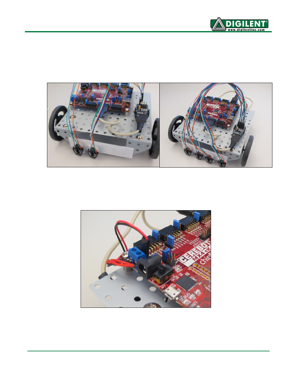
16. Attach the four IROS sensors from left to right on the Velcro mounting strip, and connect them
in the same order to each of the headers (S1-S4) on the PmodLS1. In other words, if the robot
is facing forward, and you are looking down on it from above, the sensor on your far left should
be connected to S4, the sensor at mid left should be connected to S3, the sensor at mid right
should be connected to S2, and the sensor at the far right should be connected to S1.
17. When you are ready to power the board, add four AA batteries to the battery pack, and
connect the power cable from the battery pack to the J14 battery power connector on the
Cerebot MX4cK board.
You can now use MPLAB or MPIDE to program the LineFollowingMRK
demo project to the board.
Again, this demo can be downloaded from the Line Following Motor Robot Kit product page at
digilentinc.com. Note that running the reference design requires that the power select mode jumper
J12 be shorted to External Power (EXT).