Appendix a: pictail™ plus/pim bus connections – Digilent 6021-210-000P-KIT User Manual
Page 18
Universal Development Board™ Reference Manual
Copyright Digilent, Inc. All rights reserved.
Other product and company names mentioned may be trademarks of their respective owners.
Page 18 of 27
Appendix A:
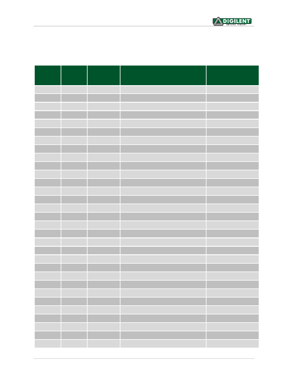
PICtail™ Plus/PIM Bus Connections
The following table, sorted by PICtail™ Plus connector pin, shows the connections between the PICtail™
connectors, the PIM socket, the on-board PIC32MX360 and the PIM headers.
PICtail™
Pin
PIM/PIC32
Pin
PIM Header
Signal
Standard Usage
1
23 J9-1, RB2
RB2/SS1/AN2
SPI1 SS
2
52 J9-2, RF2
RF2/U1RX
UART1 RXD
3
55 J9-3, RF6
RF6/SCK1
SPI1 SCK
4
51 J9-4, RF3
RF3/U1TX
UART1 TXD
5
54 J9-5, RF7
RF7/SDI1
SPI1 SDI
6
57 J9-6, RG2
RG2/SCL1
I2C1 SCL
7
53 J9-7, RF8
RF8/SDO1
SPI1 SDO
8
56 J9-8, RG3
RG3/SDA1
I2C1 SDA
9
GND
10
GND
11
25 J9-9, RB0
RB0
12
24 J9-10, RB1
RB1
13
22 J9-11, RB3
RB3/AN3
14
21 J9-12, RB4
RB4/AN4
15
GND
16
GND
17
19 J9-13, RE9
RE9/INT2
18
18 J9-14, RE8
RE8/INT1
19
47 J9-15, RD14
RD14/U1CTS
20
48 J9-16, RD15
RD15/U1RTS
21
VCC3V3
22
VCC3V3
23
VCC5V0
24
VCC5V0
25
VCC9V0
26
VCC9V0
27
90 J9-17, RG0
RG0
28
87 J9-18, RF0
RF0
29
89 J9-19, RG1
RG1
30
88 J9-20, RF1
RF1
31
N/C