3 dip bus header, 1 8-pin dip package, 2 14-pin dip package – Digilent 6021-210-000P-KIT User Manual
Page 10: 3 16-pin dip package, Dip bus header, Pin dip package
Universal Development Board™ Reference Manual
Copyright Digilent, Inc. All rights reserved.
Other product and company names mentioned may be trademarks of their respective owners.
Page 10 of 27
clock source with DIP socket IC2, or in the IC3/IC4 position to use the external clock source with either of those
sockets. Remove the shorting block from JP7 when using the internal oscillator option with the DIP device.
5.3 DIP Bus Header
The three DIP sockets are connected in parallel and wired to the DIP bus header connector, J6. Connector J6 is
used to access the I/O signals for the microcontroller being used in one of the DIP sockets. Jumper wires can be
used to connect DIP microcontroller signals from the DIP bus connector either to on-board I/O via connector J3; to
PIM bus locations via connectors J9, J10, or J11, allowing access to the PICtail™ connectors and thus PICtail™ Plus
modules; or to off-board devices.
The assignment of DIP socket pins to header pins on the DIP bus connector follows the convention for pin
numbering on DIP sockets, i.e. pin 1 is on the upper left corner to the header and the pin numbering proceeds
counter-clockwise around the pins of the header. Connector J6 is a 28-pin (2x14) header connector. It is wired
straight through for the 28-pin DIP sockets. When using the 20/14/8-pin DIP socket, or smaller DIP packages (e.g.
8-pin, 14-pin, etc.) in any of the sockets, take care to identify the correct pins to find the microcontroller signals on
the DIP bus connector.
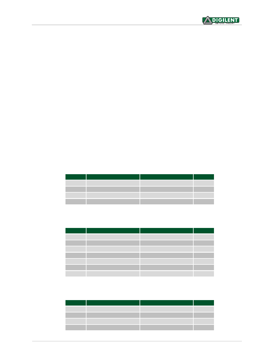
To aid in identifying which pins will be active when using smaller pin count DIP devices, vertical bars are marked on
silk screen of the board to identify the pins in use for each package size. Refer to the following tables for the
correspondence between DIP package pins and connector pins on the DIP bus connector.
5.1.1 8-Pin DIP Package
DIP Pin
DIP Bus Connector
DIP Bus Connector
DIP Pin
1
DPB-P1
DPB-P28
8
2
DPB-P2
DPB-P27
7
3
DPB-P3
DPB-P26
6
4
DPB-P4
DPB-P25
5
5.1.2 14-Pin DIP Package
DIP Pin
DIB Bus Connector
DIP Bus Connector
DIP Pin
1
DPB-P1
DPB-P28
14
2
DPB-P2
DPB-P27
13
3
DPB-P3
DPB-P26
12
4
DPB-P4
DPB-P25
11
5
DPB-P5
DPB-P24
10
6
DPB-P6
DPB-P23
9
7
DPB-P7
DPB-P22
8
5.1.3 16-Pin DIP Package
DIP Pin
DIP Bus Connector
DIP Bus Connector
DIP Pin
1
DPB-P1
DPB-P28
16
2
DPB-P2
DPB-P27
15
3
DPB-P3
DPB-P26
14
4
DPB-P4
DPB-P25
13