1 pmod connector ja, 2 pmod connector jb, 10 serial eeprom – Digilent 6021-210-000P-KIT User Manual
Page 16: Pmod connector ja, Pmod connector jb, Serial eeprom
Universal Development Board™ Reference Manual
Copyright Digilent, Inc. All rights reserved.
Other product and company names mentioned may be trademarks of their respective owners.
Page 16 of 27
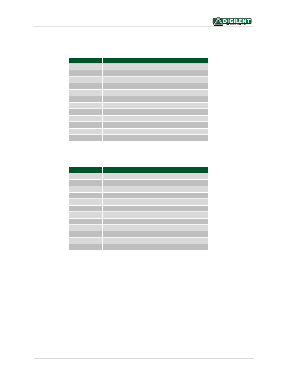
The following tables give the signal locations on the PIM bus headers to which the Pmod connector pins are wired.
9.1 Pmod Connector JA
Pmod Pin
PIM Bus Pin
Signal
JA-1
J9-21, RG9
RG9/PMPA2/SS2
JA-2
J9-27, RG8
RG8/PMPA3/SDO2
JA-3
J9-23, RG7
RG7/PMPA4/SDI2
JA-4
J9-24, RG6
RG6/PMPA5/SCK2
JA-5
GND
JA-6
VCC3V3
JA-7
J10-20, RB15
RB15/PMPA0
JA-8
J10-32, RD5
RD5/PMPRD
JA-9
J10-29, RD4
RD4/PMPWR
JA-10
J10-15, RB14
RB14/PMPA1
JA-11
GND
JA-12
VCC3V3
9.2 Pmod Connector JB
Pmod Pin
PIM Bus Pin
Signal
JB-1
J10-39, RE0
RE0/PMPD0
JB-2
J11-2, RE1
RE1/PMPD1
JB-3
J11-1, RE2
RE2/PMPD2
JB-4
J11-4, RE3
RE3/PMPD3
JB-5
GND
JB-6
VCC3V3
JB-7
J11-3, RE4
RE4/PMPD4
JB-8
J11-6, RE5
RE5/PMPD5
JB-9
J11-5, RE6
RE6/PMPD6
JB-10
J11-8, RE7
RE7/PMPD7
JB-11
GND
JB-12
VCC3V3
10 Serial EEPROM
A 25LC256 256K (32K x 8) serial EEPROM, IC7, is included for nonvolatile firmware storage. It is also used to
demonstrate the SPI bus operation. Note, this EEPROM is only present on Rev E and later boards.
This EEPROM is connected to the SPI 2 position on the PIM bus. It is connected to the signals: RG6/PMPA5/SCK2,
RG7/PMPA4/SDI2 and RG8/PMPA3/SDO2. The chip select (CS) of the EEPROM is accessed via signal RD12 on the
PIM bus.
Jumper JP1, labeled SPI EEPROM Enable, is used to enable/disable the EEPROM. Remove the shorting block on JP1
to disable the EEPROM. When the shorting block is removed, the EEPROM is held disabled and its other signals will
be tristated. When the shorting block is installed on JP1, the CS pin is connected to PIM bus signal RD12 and the
EEPROM can be enabled by driving RD12 low.