Digilent 410-155P-KIT User Manual
Page 4
Basys2 Reference Manual
Digilent
www.digilentinc.com
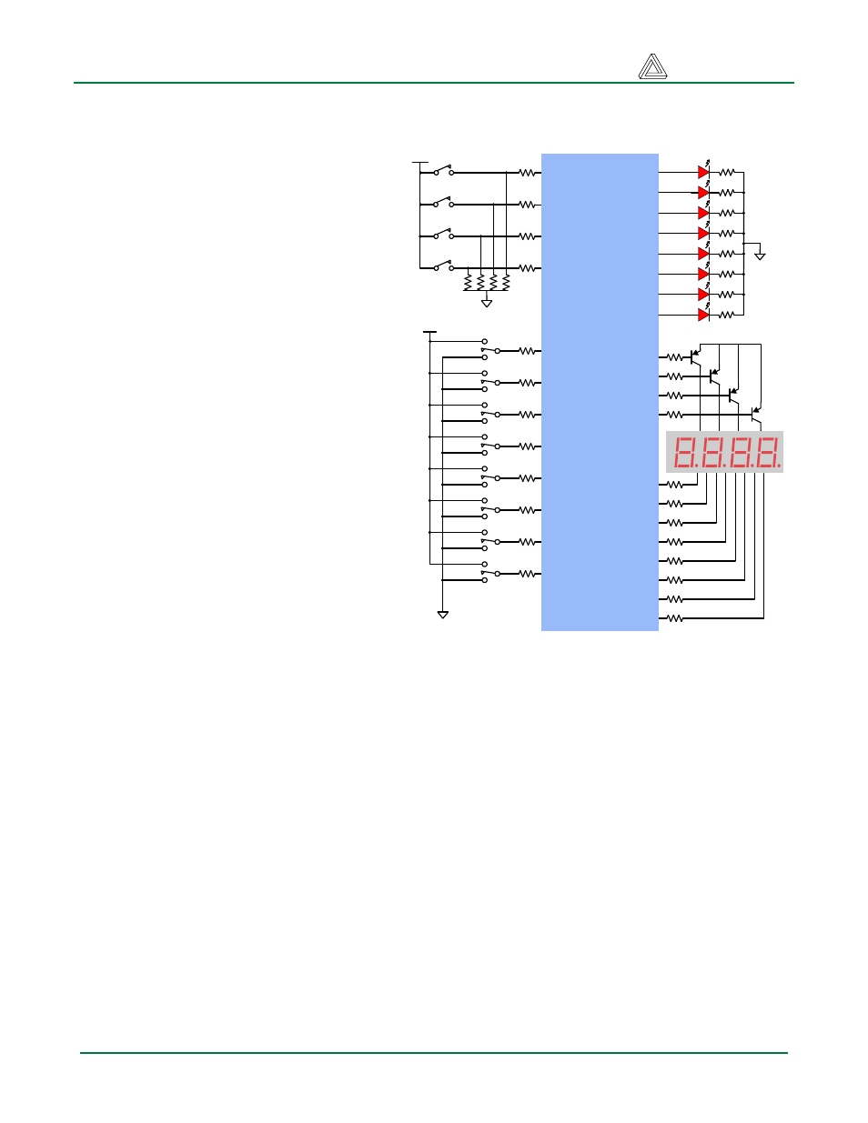
User I/O
Four pushbuttons and eight slide switches
are provided for circuit inputs. Pushbutton
inputs are normally low and driven high
only when the pushbutton is pressed.
Slide switches generate constant high or
low inputs depending on position.
Pushbuttons and slide switches all have
series resistors for protection against
short circuits (a short circuit would occur if
an FPGA pin assigned to a pushbutton or
slide switch was inadvertently defined as
an output).
Eight LEDs and a four-digit seven-
segment LED display are provided for
circuit outputs. LED anodes are driven
from the FPGA via current-limiting
resistors, so they will illuminate when a
logic ‘1’ is written to the corresponding
FPGA pin. A ninth LED is provided as a
power-indicator LED, and a tenth LED
(LD-D) illuminates any time the FPGA has
been successfully programmed.
Seven-segment display
Each of the four digits of the seven-
segment LED display is composed of
seven LED segments arranged in a “figure
8” pattern. Segment LEDs can be
individually illuminated, so any one of 128 patterns can be displayed on a digit by illuminating certain
LED segments and leaving the others dark. Of these 128 possible patterns, the ten corresponding to
the decimal digits are the most useful.
The anodes of the seven LEDs forming each digit are tied together into one common anode circuit
node, but the LED cathodes remain separate. The common anode signals are available as four “digit
enable” input signals to the 4-digit display. The cathodes of similar segments on all four displays are
connected into seven circuit nodes labeled CA through CG (so, for example, the four “D” cathodes
from the four digits are grouped together into a single circuit node called “CD”). These seven cathode
signals are available as inputs to the 4-digit display. This signal connection scheme creates a
multiplexed display, where the cathode signals are common to all digits but they can only illuminate
the segments of the digit whose corresponding anode signal is asserted.
A scanning display controller circuit can be used to show a four-digit number on this display. This
circuit drives the anode signals and corresponding cathode patterns of each digit in a repeating,
continuous succession, at an update rate that is faster than the human eye response. Each digit is
illuminated just one-quarter of the time, but because the eye cannot perceive the darkening of a digit
before it is illuminated again, the digit appears continuously illuminated. If the update or “refresh” rate
is slowed to a given point (around 45 hertz), then most people will begin to see the display flicker.
3.3V
Push
buttons
Slide
switches
Spartan 3E
FPGA
M4
C11
G12
K3
B4
G3
F3
E2
A7
N3
BTN0
BTN1
BTN2
BTN3
SW0
SW1
SW2
SW3
SW4
SW5
SW6
SW7
3.3V
LD0
LD1
LD2
LD3
LD4
LD5
LD6
LD7
3.3V
LEDs
7seg
Display
AN0
AN1
AN2
AN3
L3
P11
M5
M11
P7
P6
N5
N4
P4
G1
F12
J12
M13
K14
L14
H12
N14
N11
P12
L13
M12
CA
CB
CC
CD
CE
CF
CG
DP
N13
Figure 6. Basys2 I/O circuits
Doc: 502-138
page 4 of 12