Digilent 410-155P-KIT User Manual
Page 11
Basys2 Reference Manual
Digilent
www.digilentinc.com
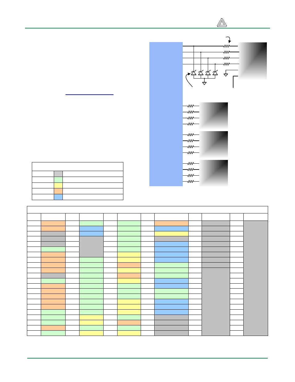
Expansion Connectors (6-pin headers)
The Basys2 board provides four 6-pin
peripheral module connectors. Each connector
provides Vdd, GND, and four unique FPGA
signals. Several 6-pin module boards that can
attach to this connector are available from
Digilent, including A/D converters, speaker
amplifiers, microphones, H-bridge amplifiers,
etc. Please see
for more
information.
FPGA Pin Definitions
The table below shows all pin definitions for the
Spartan-3E on the Basys2 board. Pins in grey
boxes are not available to the user
FPGA pin definition table color key
Grey
Not available to user
Green
User I/O devices
Yellow
Data ports
Tan
Pmod connector signals
Blue
USB signals
Basys2 Spartan-3E pin definitions
Pin
Signal
Pin
Signal
Pin
Signal
Pin
Signal
Pin
Signal
Pin
Signal
C12
JD1
P11
SW0
N14
CC
B2
JA1
P8
MODE0
M7
GND
A13
JD2
M2
USB-DB1
N13
DP
C2
USB-WRITE
N7
MODE1
P5
GND
A12
NC
N2
USB-DB0
M13
AN2
C3
PS2D
N6
MODE2
P10
GND
B12
NC
M9
NC
M12
CG
D1
NC
N12
CCLK
P14
GND
B11
NC
N9
NC
L14
CA
D2
USB-WAIT
P13
DONE
A6
VDDO-3
C11
BTN1
M10
NC
L13
CF
L2
USB-DB4
A1
PROG
B10
VDDO-3
C6
JB1
N10
NC
F13
RED2
L1
USB-DB3
N8
DIN
E13
VDDO-3
B6
JB2
M11
LD1
F14
GRN0
M1
USB-DB2
N1
INIT
M14
VDDO-3
C5
JB3
N11
CD
D12
JD4
L3
SW1
P1
NC
P3
VDDO-3
B5
JA4
P12
CE
D13
RED1
E2
SW6
B3
GND
M8
VDDO-3
C4
NC
N3
SW7
C13
JD3
F3
SW5
A4
GND
E1
VDDO-3
B4
SW3
M6
UCLK
C14
RED0
F2
USB-ASTB
A8
GND
J2
VDDO-3
A3
JA2
P6
LD3
G12
BTN0
F1
USB-DSTB
C1
GND
A5
VDDO-2
A10
JC3
P7
LD2
K14
AN3
G1
LD7
C7
GND
E12
VDDO-2
C9
JC4
M4
BTN2
J12
AN1
G3
SW4
C10
GND
K1
VDDO-2
B9
JC2
N4
LD5
J13
BLU2
H1
USB-DB6
E3
GND
P9
VDDO-2
A9
JC1
M5
LD0
J14
HSYNC
H2
USB-DB5
E14
GND
A11
VDDO-1
B8
MCLK
N5
LD4
H13
BLU1
H3
USB-DB7
G2
GND
D3
VDDO-1
C8
RCCLK
G14
GRN2
H12
CB
B14
TMS
H14
GND
D14
VDDO-1
A7
BTN3
G13
GRN1
J3
JA3
B13
TCK-FPGA
J1
GND
K2
VDDO-1
B7
JB4
F12
AN0
K3
SW2
A2
TDO-USB
K12
GND
L12
VDDO-1
P4
LD6
K13
VSYNC
B1
PS2C
A14
TDO-S3
M3
GND
P2
VDDO-1
Spartan 3E
FPGA
B2
A3
J3
B5
ESD protection
diodes
1
6-pin
header
2
3
4
5
6
JA
Short-circuit protection
resistors
3.3V
1
6-pin
header
2
3
4
JB
1
6-pin
header
2
3
4
JC
1
6-pin
header
2
3
4
JD
C6
B6
C5
B7
A9
B9
A10
C9
C12
A13
C13
D12
Figure 18. Basys2 Pmod connector circuits
Doc: 502-138
page 11 of 12