Digilent 410-155P-KIT User Manual
Page 2
Basys2 Reference Manual
Digilent
www.digilentinc.com
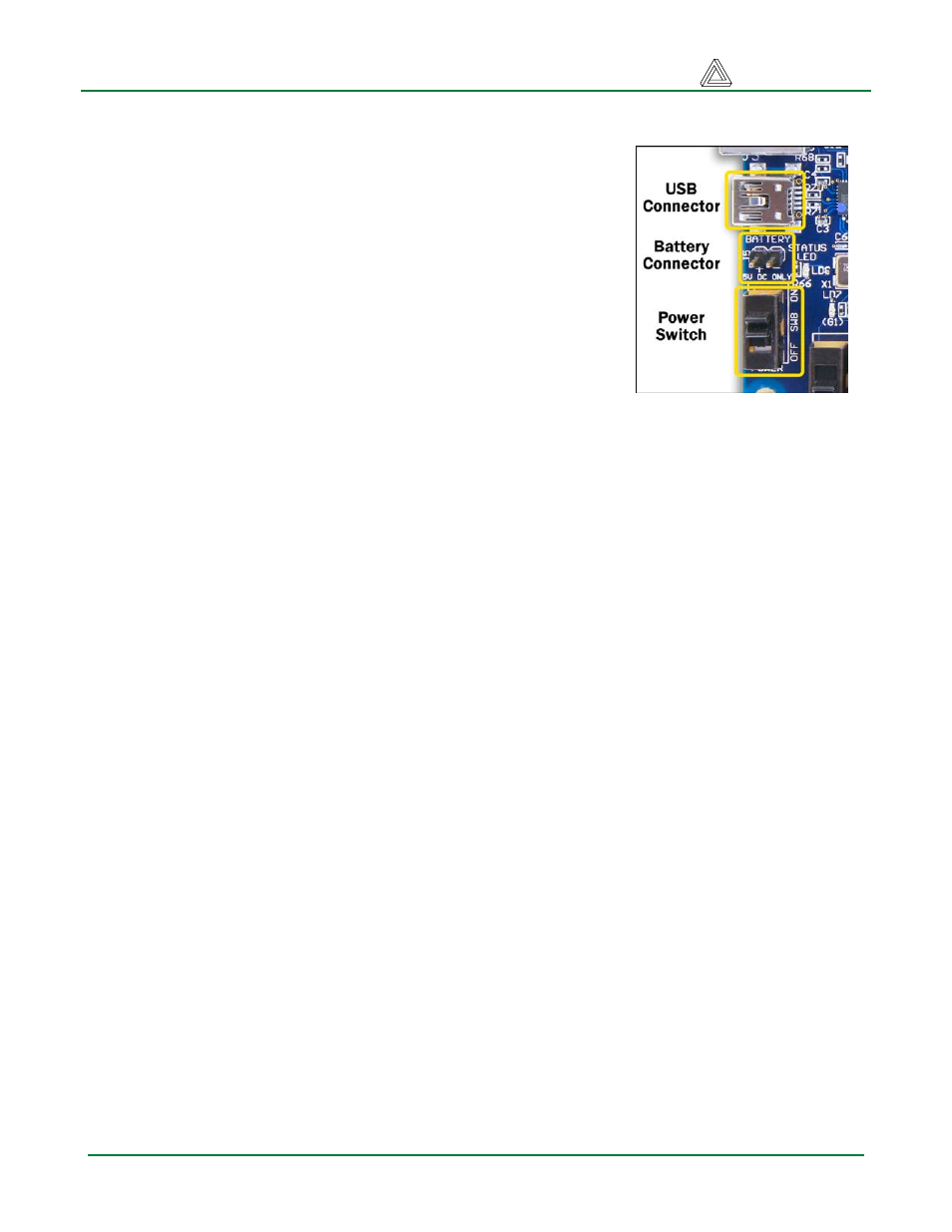
Board Power
The Basys2 board is typically powered from a USB cable, but a
battery connector is also provided so that external supplies can be
used. To use USB power, simply attach the USB cable. To power
the Basys2 using a battery or other external source, attach a 3.5V-
5.5V battery pack (or other power source) to the 2-pin, 100-mil
spaced battery connector (three AA cells in series make a good
4.5+/- volt supply). Voltages higher than 5.5V on either power
connector may cause permanent damage.
Input power is routed through the power switch (SW8) to the four
6-pin expansion connectors and to a Linear Technology LTC3545
voltage regulator. The LTC3545 produces the main 3.3V supply
for the board, and it also produces 2.5V and 1.2V supply voltages
required by the FPGA. Total board current is dependent on FPGA
configuration, clock frequency, and external connections. In test circuits with roughly 20K gates
routed, a 50MHz clock source, and all LEDs illuminated, about 100mA of current is drawn from the
1.2V supply, 50mA from the 2.5V supply, and 50mA from the 3.3V supply. Required current will
increase if larger circuits are configured in the FPGA, or if peripheral boards are attached.
The Basys2 board uses a four layer PCB, with the inner layers dedicated to VCC and GND planes.
The FPGA and the other ICs on the board have large complements of ceramic bypass capacitors
placed as close as possible to each VCC pin, resulting in a very clean, low-noise power supply.
Configuration
After power-on, the FPGA on the Basys2 board must be configured before it can perform any useful
functions. During configuration, a “bit” file is transferred into memory cells within the FPGA to define
the logical functions and circuit interconnects. The free ISE/WebPack CAD software from Xilinx can
be used to create bit files from VHDL, Verilog, or schematic-based source files.
Digilent’s PC-based program called Adept can be used to configure the FPGA with any suitable bit file
stored on the computer. Adept uses the USB cable to transfer a selected bit file from the PC to the
FPGA (via the FPGA’s JTAG programming port). Adept can also program a bit file into an on-board
non-volatile ROM called “Platform Flash”. Once programmed, the Platform Flash can automatically
transfer a stored bit file to the FPGA at a subsequent power-on or reset event if the Mode Jumper
(JP3) is set to ROM. The FPGA will remain configured until it is reset by a power-cycle event. The
Platform Flash ROM will retain a bit file until it is reprogrammed, regardless of power-cycle events.
Figure 2. Basys2 power circuits
Doc: 502-138
page 2 of 12