Fig. 5. vga horizontal synchronization – Digilent 410-258P-KIT User Manual
Page 7
Anvyl Reference Manual
www.digilentinc.com
page 7 of 16
Copyright Digilent, Inc. All rights reserved. Other product and company names mentioned may be trademarks of their respective owners.
VGA signal timings are specified, published, copyrighted and sold by the VESA organization
(www.vesa.org). The following VGA system timing information is provided as an example of how a
VGA monitor might be driven with a resolution of 640x480. For more precise information, or for
information on other VGA frequencies, refer to documentation available at the VESA website.
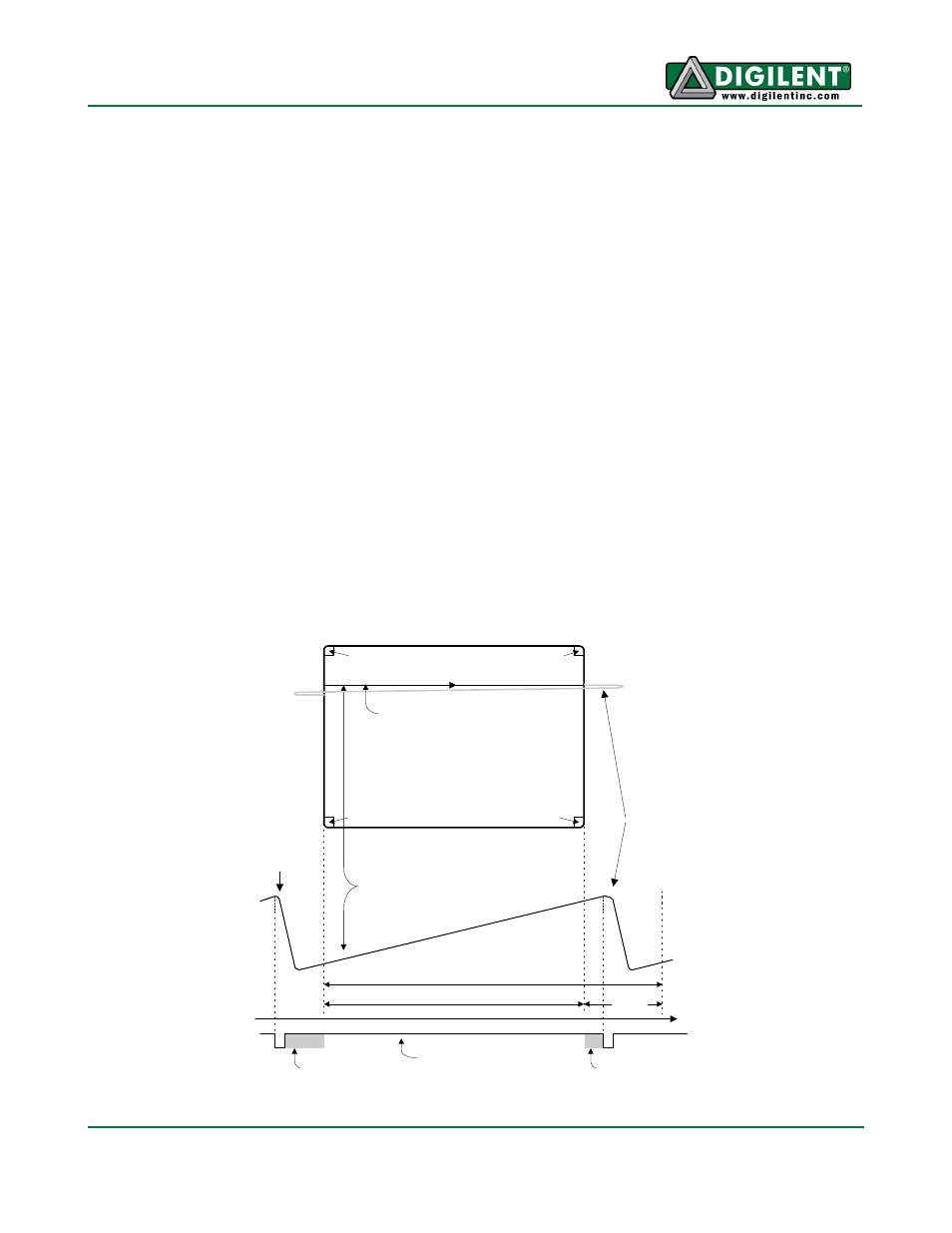
Information is only displayed when the beam is moving “forward” (left to right and top to bottom), and
not during the time the beam is reset back to the left or top edge of the display. Much of the potential
display time is therefore lost in “blanking” periods when the beam is reset and stabilized to begin a
new horizontal or vertical display pass. The size of the beams, the frequency at which the beam can
be traced across the display, and the frequency at which the electron beam can be modulated
determine the display resolution. Modern VGA displays can accommodate different resolutions, and a
VGA controller circuit dictates the resolution by producing timing signals to control the raster patterns.
The controller must produce synchronizing pulses at 3.3V (or 5V) to set the frequency at which
current flows through the deflection coils, and it must ensure that video data is applied to the electron
guns at the correct time. Raster video displays define a number of “rows” that corresponds to the
number of horizontal passes the cathode makes over the display area, and a number of “columns”
that corresponds to an area on each row that is assigned to one “picture element” or pixel. Typical
displays use from 240 to 1200 rows and from 320 to 1600 columns. The overall size of a display and
the number of rows and columns determines the size of each pixel.
Video data typically comes from a video refresh memory, with one or more bytes assigned to each
pixel location (the Anvyl uses four bits per pixel). The controller must index into video memory as the
beams move across the display, and retrieve and apply video data to the display at precisely the time
the electron beam is moving across a given pixel.
Current
through
horizontal
defletion
coil
Stable current ramp - information
displayed during this time
Retrace - no
information
displayed
during this
time
Total horizontal time
Horizontal display time
Horizontal sync signal
sets retrace frequency
retrace
time
time
HS
"back porch"
"front porch"
VGA display
surface
640 pixels are displayed each
time the beam travels across
the screen
pixel 0,639
pixel 0,0
pixel 479,0
pixel 479,639
Fig. 5. VGA horizontal synchronization.