Carl Goldberg GBGA1092 User Manual
Page 9
9
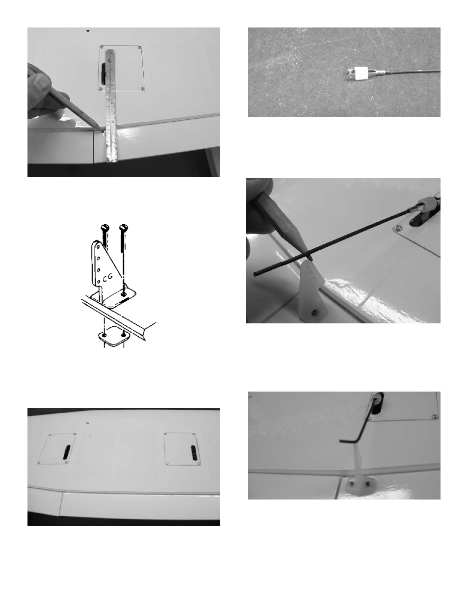
2.
Use a straight edge and make a mark at a
90º degree angle to the trailing edge and in
line with the output arm.
3.
Mount the four control horns using the #2
screws and the nylon plates on the top side
of the ailerons and flaps. The holes for the
clevis should be aligned over the hinge line.
4.
Mount the servos doors on the wing using the
#2 x 3/8” screws provided. Using the radio,
make sure the servo arm on the ailerons are
centered and the flap output arms are in the
fully up position.
5.
Screw a metal clevis on the end of each of
the four 4” pushrods. Let the threads of the
pushrod extend into the open part of the cle
vis 1/16”. Install a silicone clevis keeper on
the clevis.
6.
Install the clevis on the output arm of the
servo. Using the radio, make sure the output
arm is centered. Center the aileron and
make a mark on the pushrod where it cross-
es the control horn.
7.
Bend the pushrod 90 degrees at the mark
and cut off at 3/8”.
- GBGQ1296 (12 pages)
- GBGA1079 (25 pages)
- GPMA0963 Cub (33 pages)
- GBGA1023 (12 pages)
- GBGA1069 (29 pages)
- GPMA1956 Eagle 2 ARF (40 pages)
- GPMA0955 EAGLE 2 (59 pages)
- GBGA1080 (9 pages)
- GBGA1046 (21 pages)
- GBGA1045 (21 pages)
- GBGA1040 (16 pages)
- GBGA0040 (40 pages)
- GBGA1082 (10 pages)
- GBGA0055 (44 pages)
- GBGA1041 (20 pages)
- GBGA1070 (17 pages)
- GBGA1078 (23 pages)
- GBGA0050 (26 pages)
- GPMA1940 EP Falcon ARF (16 pages)
- GBGA0057 (60 pages)
- GPMA1960 Gentle Lady Glider ARF (16 pages)
- GPMA0960 Gentle Lady (21 pages)
- GBGA1091 (15 pages)
- GBGA1042 (9 pages)
- GBGA1019 (13 pages)
- GBGA1072 (14 pages)
- GBGA1075 (18 pages)
- GPMP1020 Mini Hold'em Electric Cradle (2 pages)
- GBGP0105 (10 pages)
- GBGA1090 (16 pages)
- GBGA1064 (24 pages)
- GBGA1088 (30 pages)
- GPMA1926 Monster Pitts Electric ARF (17 pages)
- GBGA1058 (9 pages)
- GBGA1087 (16 pages)
- GBGA1085 (19 pages)
- GPMA1993 Skylark 70 Sport ARF (18 pages)
- GPMA1959 Sophisticated Lady Glider ARF (20 pages)
- GBGA0059 (32 pages)
- GPMA1967 Sr. Falcon ARF (21 pages)
- GBGA1089 (19 pages)
- GBGA1067 (19 pages)
- GBGA0067 (39 pages)
- GBGP0108 (4 pages)