Carl Goldberg GBGA1092 User Manual
Page 8
8
2.
Pull the servo leads down through the wing
and exit through the hole on the bottom sur-
face of the wing.
AILERON FLAP CONTROL HORN
INSTALLATION
1.
Collect the following items
(4) Silicone clevis keepers
(4) nylon control horns
(4) nylon control horn nut plates
(4) 2-56 clevis
(4) 2-56 pushrods
(8) #2 screws
(4) Nylon swing in keepers
(4) 4-40 x 5-1/2” pushrods threaded both ends
IMPORTANT! To ensure that any connections located
inside the wing will not come loose, either when the
wires are pulled, or during flying, always tape them
securely together with electrical tape.
3.
Repeat these steps for the other half of the
wing, so that both servo extensions are exit-
ing the holes in the center of the wing.
4.
Mount the aileron and flap servos using the
hardware supplied with the radio. The output
arm should go toward the trailing edge.
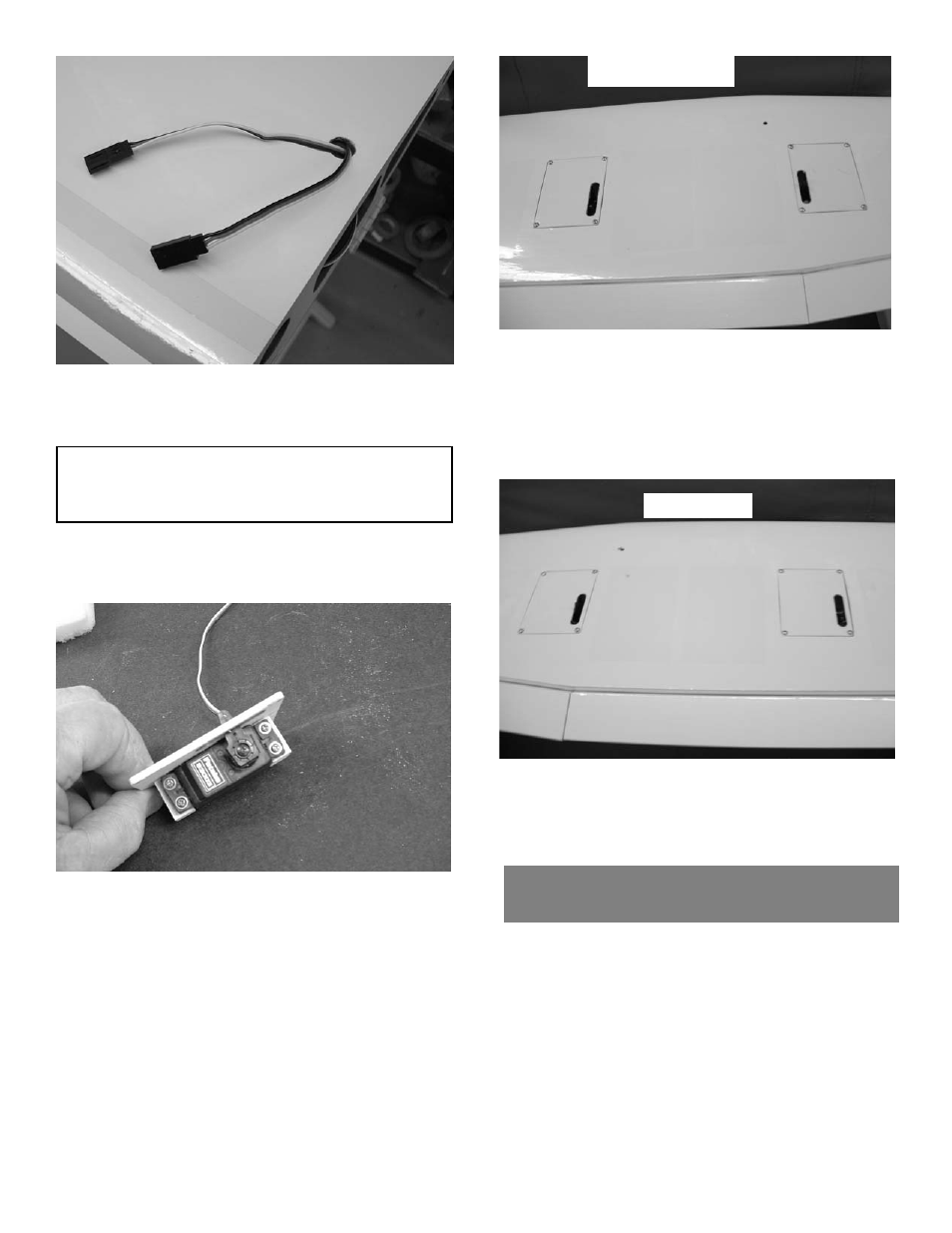
right wing
left wing
In order for the flaps and ailerons to work
properly the output arms for the servos must
be aligned as shown. On the left wing the
aileron servos output arm is on the inboard
side of the wing. The flap servo output arm
is on the outboard side of the wing.
On the right wing the aileron servo output
arm is on the inboard side of the wing and
the flap servo output arm is on the inboard
side of the wing also.