Connect your wires, Provide power – Braeburn 2200NC User Manual
Page 4
3
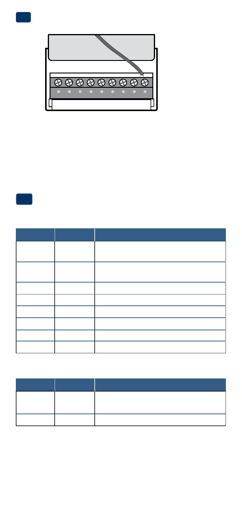
Terminal Function Description
Rc*
Input
24 Volt AC Cooling Transformer
(Dual Transformer Systems Only)
Rh*
Input
Power Connection (24 Volt AC Heating
Transformer or Millivolt Power Source)
O
Output
Reversing Valve (Cool Active)
B
Output
Reversing Valve (Heat Active)
Y
Output
Compressor Relay
(appears as
Y1 on 2200NC)
G
Output
Fan Control
W
Output
Conventional Heat Relay
C
Input
24 Volt AC Transformer Common
Connect Your Wires
3
Wiring Terminations
Terminal Function Description
W1/E
Output
(W1) 1st Stage Conventional Heat
(E) Emergency Heat Relay
W2
Output
2nd Stage Heat / Auxiliary Heat
Additional Terminations (2200NC only)
Provide Power
•
For 24 Volt AC power, you must connect the common side of the trans-
former to the C terminal on the thermostat sub-base.
•
For primary or back-up power, insert the 2 supplied “AA” type alkaline
batteries into the battery compartment located on the front of the
thermostat, near the bottom. Make sure to position the Positive (+) and
Negative (-) sides of the batteries correctly with the +/- symbols in the
battery compartment.
24VAC Power
Terminal (C)
2
C
* Appears as R on 2200NC (single transformer)
.