Avlink VX-2088 User Manual
Page 23
VX Matrix Switching System—User Manual
22
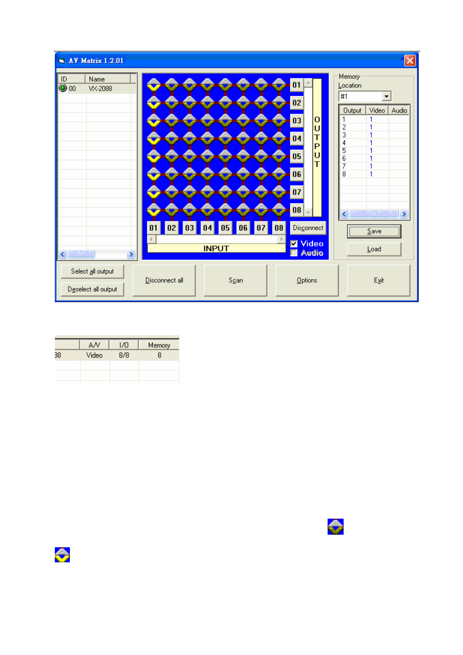
Figure 7-1 《AV Matrix》 Control Software Usage Interface
Scroll on the left lower corner to view contents as shown below.
7.0.2.1 Main Operation Interface Functions
Refer to the window menu above, the interface blue area shows crossing matrix of output
ports 01-08 and input ports 01-08. On the lower right hand corner, you can select either
“Video” for signal input switching or “Disconnect”to close all output ports. Click to check the
white box to the left of “Video” for video signal transimission.
Examples for Selecting Matrix Switching Functions:
Example 1: Now there is a VX-2088 matrix having all the input/output ports properly
connected to the equipment. There are two ways of operation if you want to set channel 1 video
to channels 2, 3 and 5 for output and channel 3 video to channel 6 for output:
First way: Directly click on the corresponding icons on the matrix
to turn them into
to complete the switching operation.
Second way:
Step 1: First select the “Output”number keys 02, 03 and 05 to the right, and select the “Input”