Tuning menu, Start sequence, Control panel operating procedures – AERCO KC1000 Heater 2002 User Manual
Page 25
CONTROL PANEL OPERATING PROCEDURES
3-7
3.7. TUNING MENU
The Tuning Menu items in Table 3-5 are Factory
set for each individual unit.
Do not change these menu entries unless
specifically requested to do so by Factory-
Trained personnel.
Table 3-5. Tuning Menu
Available Choices or Limits
Menu Item Display
Minimum
Maximum
Default
Min Load Adj
-50°F
50°F
0°F
Max Load Adj
-50°F
50°F
0°F
FFWD Temp
30°F
245°F
Outlet Feedback
On
Off
On
Reset Defaults?
Yes
No
Are You Sure?
No
3.8. START SEQUENCE
When the Control Box
ON/OFF switch is set to
the
ON position, it checks all pre-purge safety
switches to ensure they are closed. These
switches include:
• Safety Shut-Off Valve Proof of Closure
(POC) switch
• Low Water Level switch
• High Water Temperature switch
• High Gas Pressure switch
• Low Gas Pressure switch
If all of the above switches are closed, the
READY light above the ON/OFF switch will light
and the unit will be in the Standby mode.
When there is a demand for heat, the following
events will occur:
NOTE:
If any of the Pre-Purge safety device switches
are open, the appropriate fault message will be
displayed. Also, the appropriate fault messages
will be displayed throughout the start sequence,
if the required conditions are not observed.
1. The
DEMAND LED status indicator will light.
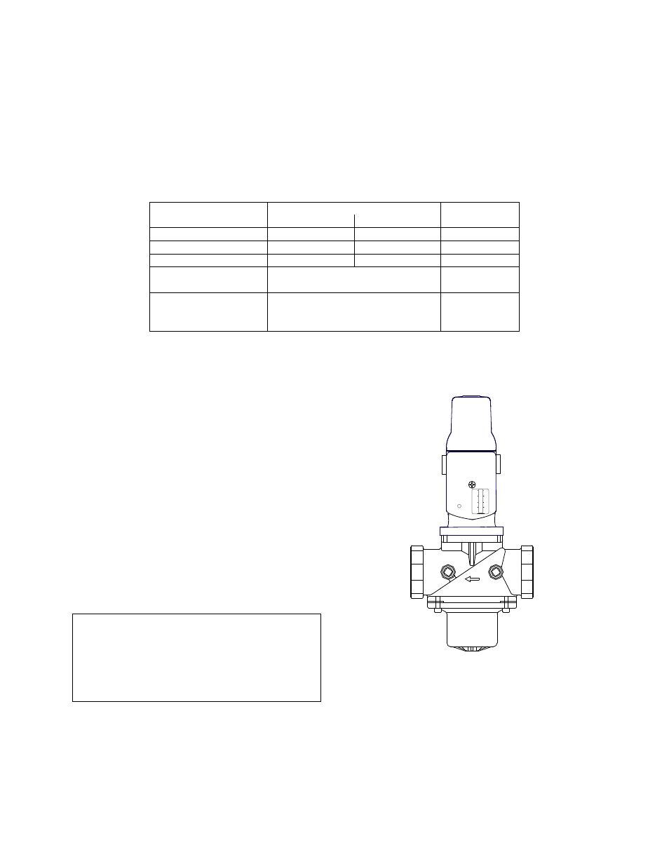
2. The unit checks to ensure that the proof of
closure switch in the Safety Shut-Off Valve
(SSOV) is closed (Figure 3-3).
Figure 3-3.
Safety Shut-Off Valve
3. With all required safety switches closed, a
purge cycle will be initiated and the following
events will occur: