Figure 2.5, Condensate drain assembly location, 4 gas supply piping – AERCO KC1000 Heater 2002 User Manual
Page 12: Figure 2.6, 1 gas supply pressure regulator, Installation
INSTALLATION
2-4
TEMPERATURE SENSOR
EXHAUST
MANIFOLD
CONDENSATE
DRAIN
BURNER
HOSE CLAMP
1-3/4" O.D. x 8-1 /2 “ LG.
SILICONE HOSE
5/8" O.D. TUBE CONN.
CONDENSATE CUP
PLACED ON FLOOR
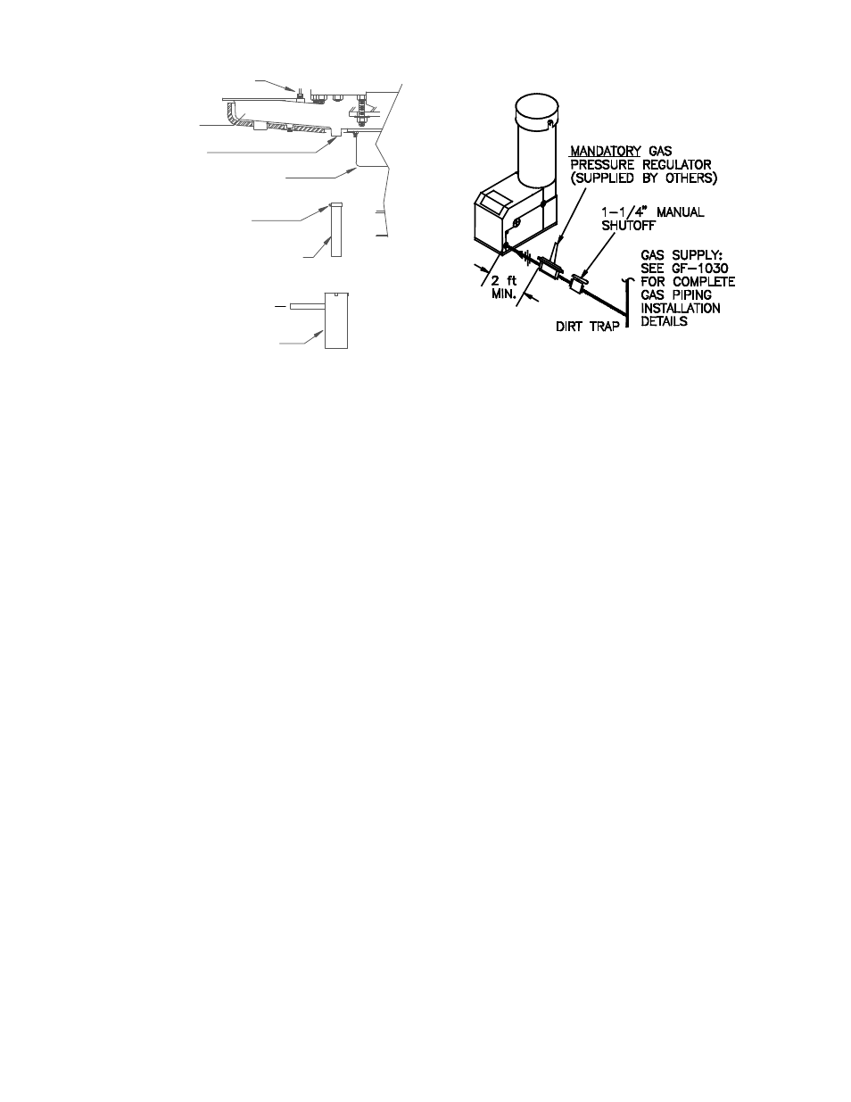
Figure 2.5
Condensate Drain Assembly Location
2.4 GAS SUPPLY PIPING
AERCO Gas Fired Equipment Gas Components
and Supply Design Guide (GF-1030) should be
consulted before any gas piping is designed or
started.
WARNING !
DO NOT USE MATCHES, CANDLES,
FLAMES OR OTHER SOURCES OF
IGNITION TO CHECK FOR GAS LEAKS
.
CAUTION !
Many soaps used for gas pipe leak testing
are corrosive to metals. The piping must be
rinsed thoroughly with clean water after leak
checks have been completed
.
NOTE:
All gas piping must be arranged so that it
does not interfere with removal of any
cover, inhibit service or maintenance, or
prevent access between the unit and walls,
or another unit
.
The location of the 1-1/4" inlet gas connection
on the right side of the unit is shown in Figure
2.6.
Figure 2.6
Gas Supply Regulator and Manual Shut -
Off Valve Location
All pipe should be de-burred and internally
cleared of any scale or iron chips before
installation. No flexible connectors or non-
approved gas fittings should be installed. Piping
should be supported from floor or walls only and
must not be secured to the unit.
A suitable piping compound approved for use
with gas should be used sparingly. Any excess
must be wiped off to prevent clogging of
components.
To avoid damage to the unit when pressure
testing gas piping, isolate the unit from the gas
supply piping. At no time should there be more
than 1 psig maximum to the unit. Bubble test all
external piping thoroughly for leaks using a soap
and water solution or suitable equivalent. The
gas piping must meet all applicable codes.
2.4.1 GAS SUPPLY PRESSURE
REGULATOR
A mandatory external, in line, supply gas regu-
lator (
supplied by others) should be positioned
as shown in Figure 2.6. Union connections
should be placed in the proper locations to allow
maintenance of the regulator if required.