Am series cascade sequencer – AERCO AM Series Boiler Cascade Sequencer Controller User Manual
Page 16
AM Series Cascade Sequencer
INSTALLATION AND OPERATION MANUAL
Setting the Logic Address for Each Heater - Continued
3. Turn the power ON to the Managing heater #1. The Cascade Sequencer will also power up.
4. Wait until the Cascade Sequencer recognizes the boiler and “E2Prom Err” is not displayed.
5. Using the Cascade Sequencer, set the Address to 1 as follows:
Logic Address Programming Procedure
a) Press and hold the Home button (Figure 2-1) for eight (8) seconds, then release the
button to display the Sub menu.
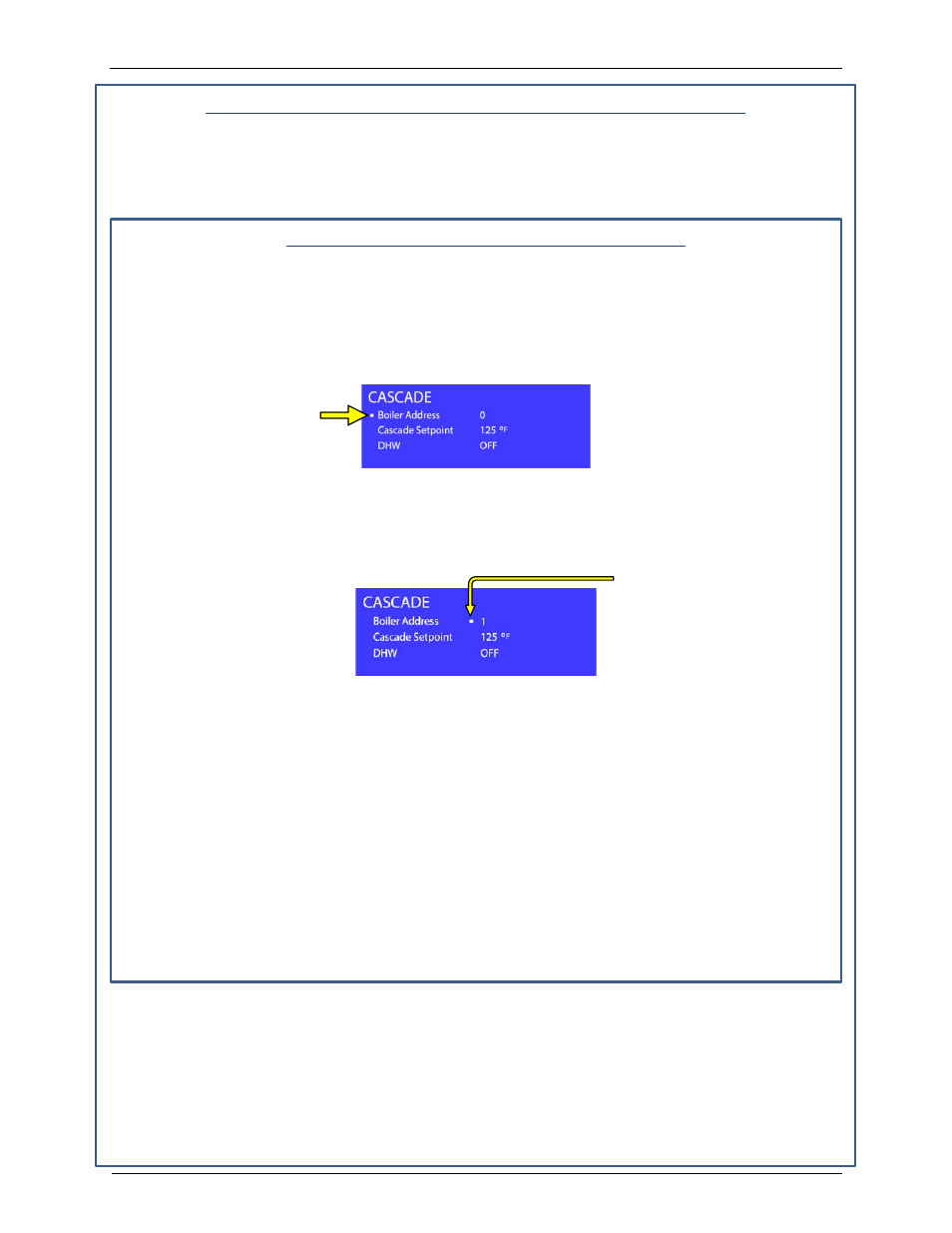
b) Once the Sub menu is displayed (Figure 1-19), use the Up or Down buttons (Figure
2-1) to scroll through the list of parameters. A dot appears to the left of the parameter
to indicate it is selected (Figure 1-19).
Figure 1-19: Sub Menu - Selecting the Parameter to Change
c) When the Boiler Address parameter is selected, press the Ok button. The dot will
then move to the left of the parameter setting (Figure 2-4), which begins to blink,
indicating it may be adjusted.
Figure 1-20: Sub Menu – Changing the Parameter Setting
d) Use the Up or Down buttons to change the parameter value up or down. For the
Managing heater, set this to 1. For each Dependent heater, a different address is set,
from 2 to 7, depending on how many dependent heaters in the cascade.
e) When the desired logic address number is displayed, save it by pressing the Ok
button
. To reject the change, do not press OK, and instead skip to the next step.
f) To return to the Main menu, press the Menu button (Figure 2-1).
g) Wait a minimum of 4 seconds or until “#1” appears in the upper left of the center box
of the sequencer display.
IMORTANT NOTE!
After any change to a parameter, wait at least 40 seconds before
exiting the sub menu or turning the power off.
6. Turn the power off to the Managing heater #1.
7. Disconnect the two wires from terminals 16 and 17 of the Managing heater #1
8. Connect the two wires from the Cascade Sequencer to terminals 16 and 17 of the
Dependent heater #2.
9. On the communications board at top of unit, set the S4 Switch (see Figure 1-13) to ON.
10. Turn the power ON to the Dependent heater #2.
Dot indicating
selected parameter
Dot indicating
parameter setting
may be changed
(Setting also blinks)
Page 16 of 26
AERCO International, Inc. • 100 Oritani Dr. • Blauvelt, NY 10913
OMM-0101_0A
PRI - 11/25/14
Ph.: 800-526-0288
GF-146-CS