5 setting the logic address for each heater, Am series cascade sequencer – AERCO AM Series Boiler Cascade Sequencer Controller User Manual
Page 15
AM Series Cascade Sequencer
INSTALLATION AND OPERATION MANUAL
Preparing the Cascade Sequencer for Use - Continued
3. Feed both wires through the rear panel conduit opening and snap rear panel onto rear of
cascade Sequencer (Figure 1-17).
Figure 1-17: Replacing Cascade Sequencer Rear Panel after Wiring
1.5 Setting the Logic Address for Each Heater
Program the logic address of each heater using the Cascade Sequencer as described below.
Setting the Logic Address for Each Heater
NOTE
Refer to Section 1.31 for location of the electrical junction
enclosure and wiring terminals mentioned below. See Section 2
for how to operate the unit and access menus and parameters.
1. Ensure power is turned OFF to the Managing heater #1.
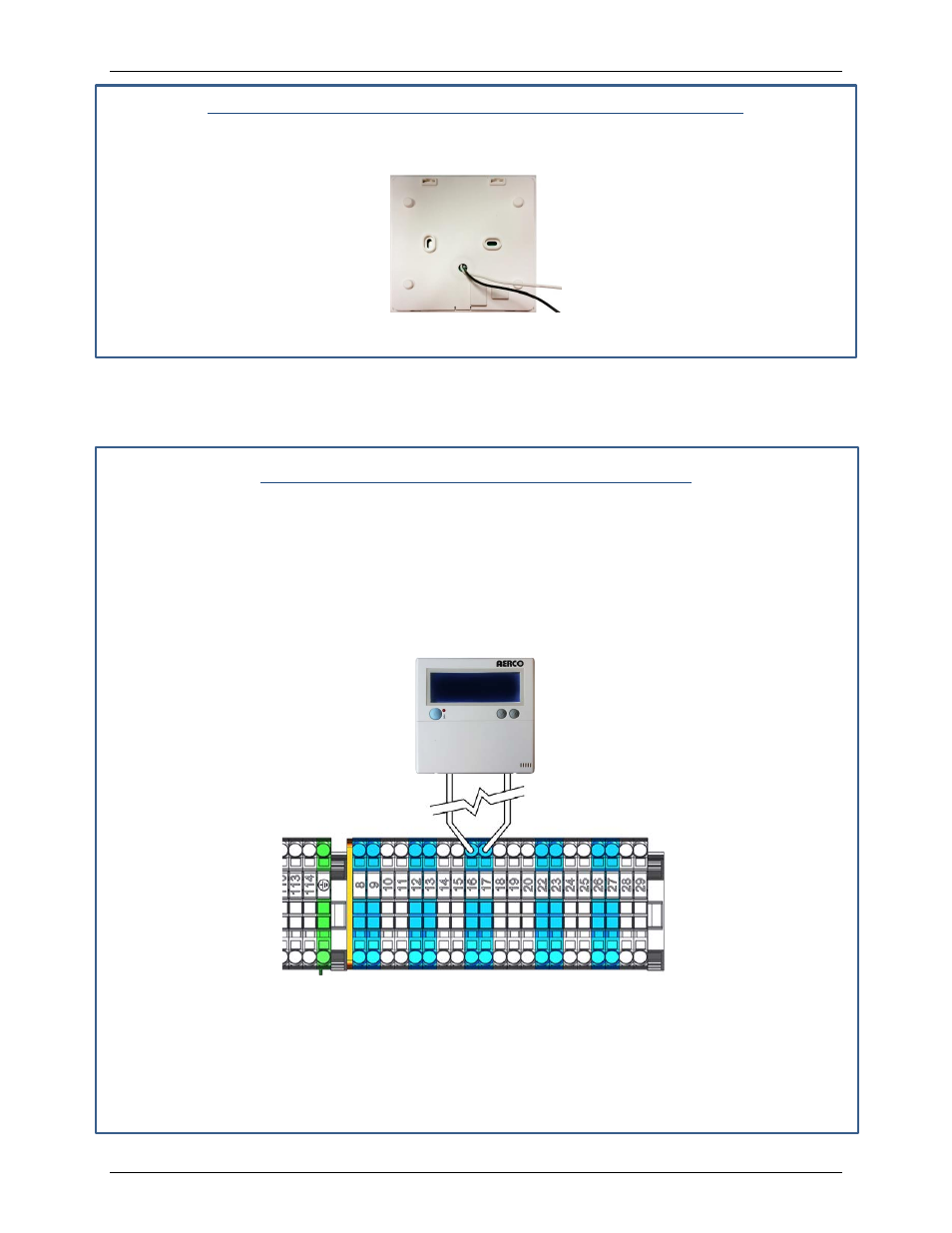
2. Connect the two wires from the Cascade Sequencer to terminals 16 and 17 of the Managing
heater # as shown in Figure 1-18.
Figure 1-18: Wiring Cascade Sequencer to Terminals 16 and 17
NOTE
The wiring diagram shown in Figure 1-18 applies to all heaters in
cascade, as each will be programmed with a unique logic address
using the Cascade Sequencer. Other wiring is not shown for
clarity.
OMM-0101_0A
AERCO International, Inc. • 100 Oritani Dr. • Blauvelt, NY 10913
Page 15 of 26
GF-146-CS
Ph.: 800-526-0288
PRI - 11/25/14