Settings for sj-ha units in coupled operation, Frequency setting, Connecting sj-ha series units in coupled operation – KEYENCE SJ-HA Series User Manual
Page 6: Op-84296 relay box, Maintenance of electrode probes, Caution, Warning
6
Settings for SJ-HA Units in Coupled Operation
Using the coupled Relay Box, more than one SJ-HA Series can be used by coupling in parallel.
When using SJ-HA units in coupled operation, set a unique frequency for each SJ-HA unit individu-
ally.
Do not connect a number of power supplies to a single SJ-HA unit or more than one SJ-HA
unit connected together, otherwise the power supplies will be short-circuited an accident or
malfunction may result.
• A coupled installation of the SJ-HA units is possible under the following restrictive conditions.
• Up to seven SJ-HA units can be connected.
• The total extension length between the power supply and the farthest static elimination bar is within
30 m.
• When providing air to more than one SJ-HA unit, check that each static elimination bar is provided with
air. If the air supply source is one, each static elimination bar may not be provided with enough air.
Up to seven SJ-HA units can be connected in parallel over the optional 10-to-10-pin serial cable
through the optional OP-84296 relay box.
Using the OP-84296 relay box allows the SJ-HA Series to be con-
nected in parallel.
Use the relay box (OP-84296) as well when extending the cable.
• Set the terminator switch to "2" if the SJ-HA Series is connected to the OUT port of the relay box.
• Set the terminator switch of the OUT port that is not connected to the SJ-HA Series to "1".
Do not connect a number of power supplies to a single SJ-HA unit or more than one SJ-HA
unit connected together, otherwise the power supplies will be short-circuited an accident or
malfunction may result.
• A coupled installation of the SJ-HA units is possible under the following restrictive conditions.
• Up to seven SJ-HA units can be connected.
(Seven units can be connected only when using the power supply of 36 V. When using 24 V, contact
your nearest KEYENCE sales office.)
• The total extension length from the power supply to the farthest static elimination bar must be less
than 30 m.
• When providing air to more than one SJ-HA unit, check that each static elimination bar is provided with
air. If the air supply source is one, each static elimination bar may not be provided with enough air.
Maintenance of Electrode Probes
When the SJ-HA Series is used for a long period, the electrode probes become dirty due to the accu-
mulation of dust.
If you continue to use the SJ-HA Series with dust accumulating on the electrode probes, the static
elimination ability may deteriorate, resulting in an accident or product breakdown. Therefore, be sure
to clean the electrode probes periodically.
Use the electrode probe cleaning kit (OP-84299) or a cotton swab when performing maintenance for
the electrical probes.
• Turn off the SJ-HA Series before the maintenance of the electrode probes.
• Do not touch the electrode probes directly with your hand or fingers, as this may cause
injury. Be extremely careful when cleaning them.
■
Cleaning the electrode probes : Electrode probe cleaning kit (OP-84299)
Soak the filter of the cleaning kit with alcohol, and place the cleaning kit on the electrode probe and
rotate it gently two or three times.
The filter on the cleaning kit will remove any dirt from the electrode probes. Replacement filters
(OP-42218) are also available.
* For information on how to replace the filter, see "Electrode Probe Cleaning Kit Instruction Manual".
■
Clean the electrode probe : Cotton bud
Clean the electrode probe with a cotton bud moistened with alcohol.
■
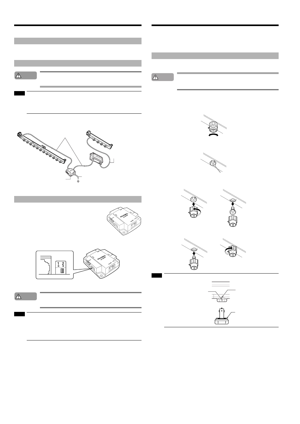
Changing the electrode probes
Place the included electrode probe replacement kit over the electrode probe and press it towards the
device while rotating it counter-clockwise to remove the electrode probe.
To attach an electrode probe, place the new probe in the electrode probe replacement kit, line it up
with the grooves and insert it. Press the kit towards the device and turn clockwise to secure the elec-
trode probe.
• When attaching an electrode probe, line up the markings on the device and the markings on the electrode
probe.
• When attaching an electrode probe, check that the O-ring is at the designated position.
Frequency setting
Connecting SJ-HA Series units in coupled operation
OP-84296 relay box
Caution
NOTE
DC power supply at a rated
voltage of 24 to 36 V.
Relay box
10-to-10-pin cable
10-to-10-pin cable for
SJ-H036A
10-pin I/O cable
Caution
NOTE
Maintenance of electrode probes
Warning
NOTE
Device markings
Electrode probe markings
O-ring