Connection of power supply, Static elimination setting, Frequency setting – KEYENCE SJ-HA Series User Manual
Page 4: Caution
4
■
Connecting SJ-H060A/084A/108A/132A/156A/180A/204A/228A/252A/300A to
power supply
A 10-pin I/O cable (sold separately) is required to connect the SJ-H060A/084A/108A/132A/156A/
180A/204A/228A/252A/300A to power supply.
1
See “Wiring diagram” (page 3) and connect each wire of the 10-pin I/O cable.
• For proper static elimination, the ground wire must be grounded at a resistance not
exceeding 100
Ω.
• Use a DC power supply with a marginal output (at least 500 mA) at a rated voltage of 24 to
36 V.
• Do not connect a number of power supplies to a single SJ-HA unit or more than one SJ-
HA unit connected together, otherwise the power supplies will be short-circuited an acci-
dent or malfunction may result.
2
Connect the modular connector of the 10-pin I/O cable to
the SJ-H060A/084A/108A/132A/156A/180A/204A/228A/
252A/300A.
SJ-H060A/084A/108A/132A/156A/180A/204A/228A/252A/
300A have the cable connection part (10-pin).
The connector will snap when it is connected correctly.
• Press the tab of the modular connector to disconnect the cable. Do not pull the cable with-
out pressing the tab, otherwise the cable may be damaged.
• Keep a space of at least 10 mm around the static elimination bar after installation, other-
wise the static elimination bar may malfunction or receive damage.
■
Connecting SJ-H036A to power supply
A 10-pin I/O cable and a 10-to-10-pin cable (both sold separately) are required to connect the
SJ-H036A to power supply.
1
See “Wiring diagram” (page 3) and connect each wire of the 10-pin I/O cable.
• For proper static elimination, the ground wire must be grounded at a resistance not
exceeding 100
Ω.
• Use a DC power supply with a marginal output (at least 500 mA) at a rated voltage of 24 to
36 V.
• Do not connect a number of power supplies to a single SJ-HA unit or more than one SJ-
HA unit connected together, otherwise the power supplies will be short-circuited an acci-
dent or malfunction may result.
2
Connect the modular connector of the
10-pin I/O cable to the SJ-H036A controller.
Connect the cable to the cable connection part indicated
“GRAY” on the controller.
The connector will snap when it is connected correctly.
3
Connect the SJ-H036A controller and the static elimina-
tion bar over the 10-to-10-pin cable.
Connect the cable to the connector marked by the word
"BLACK." Then connect the cable to the static elimination bar
of the SJ-H036A.
The connector will snap when it is connected correctly.
• Press the tab of the modular connector to disconnect the cable. Do not pull the cable with-
out pressing the tab, otherwise the cable may be damaged.
• Keep a space of at least 10 mm around the static elimination bar after installation, other-
wise the static elimination bar may malfunction or receive damage.
The SJ-H036A static elimination bar and controller should bear the same serial number. Check that
they bear the same serial number when connecting them.
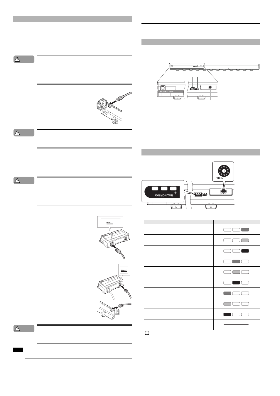
Static Elimination Setting
This section provides the name and functions of operation keys, switches, and indicators on the con-
troller’s front panel. It also describes the operation procedure for the static elimination setting.
The control panel of the SJ-H084A/108A/132A/156A/180A/204A/228A/252A/300A has the same lay-
out.
The control panel of the SJ-H060A and SJ-H036A has the setting switch and display part positions
swapped.
1. FREQ switch....... Sets the frequency
2. ION MONITOR ... Displays the strength of the electric charge of the object.
3. Alarm Indicator... This flashes once per second if static elimination power is affected by situations
such as an absorption of ions by surrounding metals, which can cause instabil-
ity of the setting environment (temperature, humidity, surrounding metals).
(Condition alarm) This will blink twice per second if the ion generation capability
falls below the set value due to wear or dirt on the electrode probe.
(Ion level alarm) Flashes if the quantity of ion generation is low due to the deteri-
oration of the electrode probes or the dirt on the electrode probes. Then static
elimination will be forcibly turned OFF. (Alarm)
A frequency is set with the FREQ switch in the SJ-HA Series.
When the frequency setting is made, the indicator for the present frequency on the ION MONITOR
will flash for approximately five seconds. Then the indicator will be turned OFF.
For frequency settings in detail, see “Static elimination ability” (page 2).
Connection of power supply
Caution
Caution
Caution
Caution
NOTE
Names and functions of operation keys, switches, and indicators
Frequency setting
Frequency
FREQ. switch
ION MONITOR
68Hz
0
OFF
OFF
Green
47Hz
1
OFF
OFF
Yellow
33Hz
2
OFF
OFF
Red
22Hz
3
OFF
Green
OFF
10Hz
4
OFF
Yellow
OFF
8Hz
5
OFF
Red
OFF
5Hz
6
Green
OFF
OFF
3Hz
7
Yellow
OFF
OFF
1Hz
8
Red
OFF
OFF
Not used
9
1
2
3