Installing sj-ha series, Wiring diagram (sj-c2u/c5u/c10u 10-pin i/o cable), Caution – KEYENCE SJ-HA Series User Manual
Page 3
3
■
Interference
The SJ-HA Series may not operate properly if there is any conductive object close to the SJ-HA
Series or if another SJ-HA unit is installed closely together. Refer to the following illustration and iso-
late the SJ-HA Series from the conductive object.
If two SJ-HA units are used, refer to the following illustration and separate the static elimination bars
properly.
■
Auxiliary support part (SJ-H132A/156A/180A/204A/228A/252A/300A)
Install the SJ-H132A/156A/180A/204A/228A/252A/300A with auxiliary support part. Auxiliary support
part prevents the static elimination bar from bending. Do not install the SJ-H132A/156A/180A/204A/
228A/252A/300A without using auxiliary support part.
■
Cables
The cables, including power cables and connector cables, required for the SJ-HA Series are not
included in the package. Confirm the installation location before installing and make sure to buy the
proper lengths of cables (10 pin I/O cable, 10-to-10-pin cable and 10-to-10-pin for SJ-H036A
cables).
■
Installing SJ-HA Series
Install the SJ-HA Series in places where a static problem occurs or may occur.
• When installing the SJ-H132A/156A/180A/204A/228A/252A/300A, mount and secure the
auxiliary support parts with screws for the prevention of the static elimination bar from
bending, otherwise the static elimination bar may be broken.
See “Precautions for installation” (page 2).
• Keep a space of at least 10 mm around the static elimination bar after installation, other-
wise the static elimination bar may malfunction or receive damage.
1
Mount the auxiliary support parts on top of the static elimination bar or along the guide rails.
The SJ-H132A/156A/180A/204A requires a single auxiliary support part, the SJ-H228A/252A/
300A requires two auxiliary support parts. Mount them at approximately equal intervals.
Confirm that the hooks on the auxiliary support part grasp the guide rails on the static
elimination bar when installing.
2
Attach the end unit to each end of the static elimi-
nation bar.
3
Secure the SJ-HA Series with M4 screws at the
desired installation position.
When installing the SJ-H132A/156A/180A/204A/
228A/252A/300A, secure the auxiliary support
part with M4 screws as well.
When removing the auxiliary support part, be sure to
remove it from the side along the guide rails.
* The blue wire and orange wire are insulated from each other.
* There are two wires each for the brown wire and the blue wire.
Be sure to connect both of the two wires. The ends are sol-
dered together before shipping.
Do not short-circuit the output signal wire and output signal GND wire together without any
load, otherwise the internal circuit will be damaged, which may result in product
malfunctions, because the SJ-HA Series does not have any overcurrent protection circuit.
■
Input circuit
■
Output circuit
Type
No. of auxiliary support parts necessary
for installation
SJ-H036A/060A/084A/108A
0
SJ-H132A/156A/180A/204A
1
SJ-H228A/252A/300A
2
Item
Type
Appearance
Description
10-pin I/O cable
SJ-C2U (2m)
SJ-C5U (5m)
SJ-C10U (10m)
Power cable for the SJ-HA
Series. Three types (2-, 5-,
10-m cables) are available.
(Cable color :Gray)
10-to-10-pin cable
OP-42210 (2m)
OP-42211 (5m)
OP-42212 (10m)
Cable for connecting the SJ-
HA Series units. Three types
(2-, 5-, 10-m cables) are
available. Use this cable to
connect to the coupled Relay
Box. (Cable color :Gray)
10-to-10-pin cable
for SJ-H036A
SJ-C2H (2m)
SJ-C5H (5m)
SJ-C10H (10m)
The cable that connects the
SJ-H036A controller to the
bar. Three types (2-, 5-, 10-m
cables) are available. 10-pin
I/O cable is necessary for
supplying power.
(cable color :Black)
Relay box
for SJ-HA
OP-84296
This is required if the cables
will extend more than 10
meters. (For use with the
10-to-10-pin cable)
Installing SJ-HA Series
200 mm
min.
200 mm
min.
150 mm min.
150 mm
min.
150 mm
min.
400 mm
min.
100 mm
min.
Side-to -side installation
Face-to-face installation
Caution
Caution
•
Mounting from the side
•
Mounting from the top
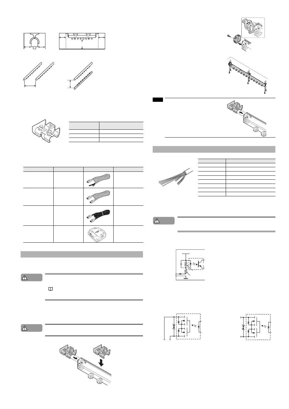
Wiring diagram (SJ-C2U/C5U/C10U 10-pin I/O cable)
Cord color
Description
Brown (2 wires)
DC power supply (rated voltage of 24 to 36 V)
Blue (2 wires)
Power supply GND
Pink
Static elimination interrupt input
Orange
Output signal GND
Black
Ion level alarm output
White
Condition alarm output
Gray
Alarm output
Shield wire (thick black wire)
Ground (Ground at a resistance not exceeding 100
Ω.)
NOTE
Caution
[Pink (Static Elimination Interrupt Input)]
Apply NPN open collector input to the INPUT
and 0 V terminals from non-voltage contacts
(such as relays).
INPUT (Pink)
0V (Blue)
2.7 k
Ω
2.4 k
Ω
VCC (Power supply)
Photo Relay Output
[Black (Ion Level Alarm Output),
White (Condition Alarm Output)]
Photo Relay Output
[Gray (Alarm Output)]
OUT
DC40 V
100 mA
ALM
Output GND
Output GND