Center indicator, Interlock function, Temporary suspension of safety function – KEYENCE SL-VHS Series User Manual
Page 7: Nomenclature, Dimensions and specifications, Sl-vhs-im-e, Nomenclature dimensions and specifications, Sl -v 12 hs t
7
SL-VHS-IM-E
With the SL-VHS, OSSD automatically turns ON upon startup (when the power turns on or the lockout
error condition is terminated by reset input) or restart (when the SL-VHS is blocked and OSSD turns
OFF) if no interruption is present in the detection zone. Therefore, safety must be secured by combin-
ing a device that connects OSSD (such as safety relay unit), or a machine that prevents entrance to
the hazardous zone merely by passing through the protection zone or detection zone of the SL-VHS.
■
Muting Function
The muting function is used to temporarily suspend the SL-VHS's safety functions while the SL-VHS
receives a signal from one or more muting devices (such as sensors or switches). Before this function
can be used, the outputs from the muting devices must be connected to the muting input terminal on
the SL-VHS.
●
Muting device
When using the muting device, it must meet the following conditions.
• The muting device output must be N.O. (normal open).
• Output of the muting device must be the output with contacts, and must be PNP output type if
PNP output type cable is used, or NPN output type if NPN output type cable is used. Also, the
muting device must be capable of 2 to 3 mA current.
• Do not use one muting device with multiple outputs in place of two or more muting devices.
(Only one output can be used per muting device.)
• If the muting device has a timer function that can adjust the output timing, do not use that func-
tion.
●
Muting lamp
When using the muting lamp, it must meet the following conditions.
For an incandescent lamp
: rated 24 VDC, 1 to 7 W
For LED indicator
: rated current consumption must be 10 to 300 mA.
If the incandescent lamp burns out, or if the lamp used does not meet the above conditions, the
state information output shows a muting lamp error.
●
Conditions for initiation of muting
Muted condition is initiated if all of the following conditions are met.
• Muting input 2 turns ON within 0.04 to 3 seconds after muting input 1 turns ON
• SL-VHS detects no interruption in the detection zone
• OSSD is ON state.
●
Conditions for termination of muting
Muted condition is terminated if one of the following conditions is met.
• Either of muting inputs goes to OFF state at least for more than 0.02 sec.
• Light curtain goes to lockout condition
• Wait input goes to ON state
• The power supply is interrupted or restored.
• Maximum muting period of approx. 5 minutes has been passed.
■
Override function
The OSSD goes to an OFF state if the muting function is deactivated and an interruption remains in
the detection zone of the SL-VHS. The OSSD OFF state will remain until the obstruction is removed.
The override is a function to allow a temporary manual suspension of the SL-VHS safety functions.
This makes it possible to remove the obstruction remaining in the detection zone of the SL-VHS.
(Machine is able to be manually operated on a temporary basis because the safety function of the
SL-VHS is temporarily suspended.)
●
Conditions for initiation of override
Override function is initiated if all of the following conditions are met and the reset input goes to
ON state within 0.04 to 1 seconds after override input turns ON state.
• SL-VHS is not in the lockout condition.
• SL-VHS detects interruption in the detection zone. (One or more beam axis is blocked.)
• OSSD is OFF state. (including interlock condition)
• Either of muting inputs, or both, turns ON state
●
Conditions for termination of override
Override function is terminated if one of the following conditions is met.
• All of muting inputs turn OFF state.
• Either override input or reset input, or both, turns OFF state.
• Light curtain goes to lockout condition
• Wait input turns ON state.
• Maximum override period of approx. 60 seconds has been passed.
(1) Basic designation
: SL-V
(2) The number of beam axes
Example
: "08" means
→ 8 axes, "64" means → 64 axes
(3) Detection capability
HS
:
φ
25 mm
(4) Transmitter and receiver
T : Transmitter
R : Receiver
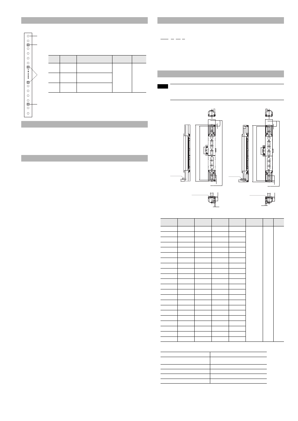
If the length for a single SL-VHS unit is 710 mm or greater, use a compact E-to-E mounting bracket or
an E-to-E mounting bracket additionally as an intermediate support bracket. The following figures show
the example for the use of one compact E-to-E bracket or space-saving bracket.
Units: mm
Units: mm
■
Parameter for IEC61508
*1
For PFHd of each SL-V, contact your nearest KEYENCE office.
Center Indicator
Interlock Function
Temporary Suspension of Safety Function
Beam axis
Center
indicator
(Upper)
Center
indicator
(Lower)
Center
indicator
(Middle)
Center indicator (Upper) : indicates whether interruption is present in the top
beam axis or not. (clear or blocked)
Center indicator (Middle) : indicates whether the middle axis beams are interrupted
or not. The SL-V08HS does not have this indicator.
Center indicator (Lower) : indicates whether interruption is present in the bottom
beam axis or not. (clear or blocked)
Center
indicator
Light OFF
red light
green light
Blinking red
light
Upper
Top beam axis
is blocked
Although the top beam axis is
unblocked, the others are
blocked
No interruption is
present in
detection zone of
the SL-VHS.
(clear)
Lockout
condition
Middle
Middle beam
axis are
blocked
Although the top and bottom
beam axis are unblocked, the
middle beams are blocked
Lower
Bottom beam
axis is blocked
Although the bottom beam axis is
unblocked, the others are
blocked
Nomenclature
Dimensions and Specifications
Model
Beam axes
A: Length
B: Detection
height
C: Protection
height
D: Beam axis
spacing
E
F
SL-V08HS
8
150
140
185
20
5
22.5
SL-V12HS
12
230
220
265
SL-V16HS
16
310
300
345
SL-V20HS
20
390
380
425
SL-V24HS
24
470
460
505
SL-V28HS
28
550
540
585
SL-V32HS
32
630
620
665
SL-V36HS
36
710
700
745
SL-V40HS
40
790
780
825
SL-V44HS
44
870
860
905
SL-V48HS
48
950
940
985
SL-V52HS
52
1030
1020
1065
SL-V56HS
56
1110
1100
1145
SL-V60HS
60
1190
1180
1225
SL-V64HS
64
1270
1260
1305
SL-V72HS
72
1430
1420
1465
SL-V80HS
80
1590
1580
1625
SL-V88HS
88
1750
1740
1785
SL-V96HS
96
1910
1900
1945
SL-V104HS
104
2070
2060
2105
SL-V112HS
112
2230
2220
2265
SL-V120HS
120
2390
2380
2425
T1 (Proof test interval)
20 years
PFHd (average frequency of a dangerous
failure per hour)
*1
With no series connection: 8.2 x 10
-9
or less
With series connection: 1.7 x 10
-8
or less
Hardware fault tolerance
1
Type of element
Type B
Failure response time
Within a response time
Safe state
OSSDs are in OFF-state
SL -V 12 HS T
(1)
(2)
(4)
(3)
NOTE
9
28.8
12
4.3
28
A
B
14
4.5
F
E
C
D
5
φ5.8 Cable
6-M3 Depth 4.5
12
4.3
28.8
28
14
4.5
A
B
F
E
C
D
5
9
φ5.8 Cable
6-M3 Depth4.5
Transmitter
Receiver