Bar led indicator, Sl-vhs-im-e, Start-up after turning on power – KEYENCE SL-VHS Series User Manual
Page 6: During normal operation, Function indicators
6
SL-VHS-IM-E
■
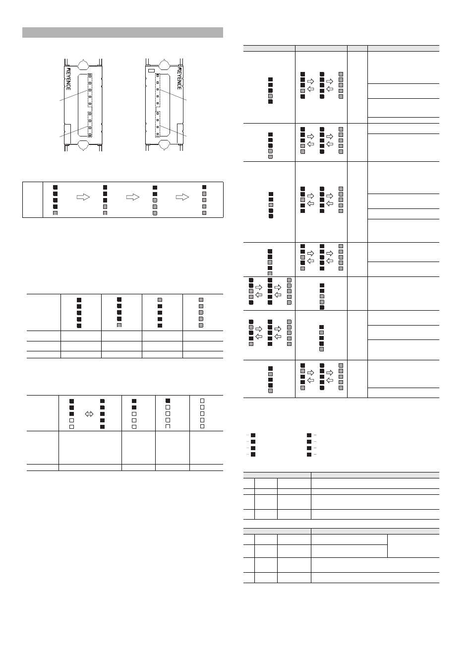
Start-up after turning on power
The bar LEDs 1 to 4 light up in the following sequence during start-up (approx. 4.5 s). The other indi-
cators are all off. The indicators show the same indication between the transmitter and receiver.
■
During normal operation
●
When the interruption is present in the detection zone (one or more beam axis is
blocked.)
The state of bar LEDs No.1 to No. 5 means as follows.
No. 5
: It lights in red when no interruption is present in the top beam axis. (clear)
No. 2 to No. 4 : It does not light when the interruption is present in either the top or bottom beam
axis (blocked). On the other hand, it lights in red when no interruption is present in
both the top and bottom beam axes (clear) and the interruption is present in any
other beam axis. (blocked)
No. 1
: It lights in red when no interruption is present in the bottom beam axis. (clear)
The indicators show the same indication between the transmitter and receiver.
Indication pattern
●
When no interruption is present in the detection zone
The bar LEDs No.1 to No. 5 means as follows. They indicate the number of beam axes with the
amount of receiving light of 140 % or greater. The indicators show the same indication between
the transmitter and receiver.
Indication pattern
For the definition of the amount of receiving light of 100 %, 100 % means a threshold between OSSD-
ON and OSSD-OFF.
In case of around 100 %, the light curtain easily goes to ON state or OFF state due to environmental or
installation factor, such as dust, pollution, angle, vibration or the like.
●
During lockout condition
If the SL-VHS has detected any kind of irregularity, the OSSD (control output) will lock itself in the
OFF state. When this occurs, bar LEDs 1 through 5 will indicate the source of the problem and the
center display light will blink red.
To end the lockout condition, solve the source problem and send reset output or turn the device
off and then back on again. Try the following measures.
Bar LED indicators
When using multiple SL-Vs in series, the SL-VHS which triggers the lockout condition will indicate
using bar LEDs 1-3 while the other SL-VHS will only use bar LED 1.
*1 Blinking cycle of each indicator output may be longer.
*2 All indicators on the transmitter may turn OFF.
■
Function Indicators
Transmitter
Receiver
Transmitter
Receiver
*1 For the interval of blinking, lights for 2 seconds, and turns off for 0.3 seconds. In other cases, lights for 0.3 seconds and
also turns off for 0.3 seconds.
Bar LED Indicator
Bar LED
indicator
Indication
Top beam axis
Blocked
(Interrupted)
Blocked
(Interrupted)
Clear
(Not interrupted)
Clear
(Not interrupted)
Bottom beam axis
Blocked
(Interrupted)
Clear
(Not interrupted)
Blocked
(Interrupted)
Clear
(Not interrupted)
OSSD state
OFF
OFF
OFF
OFF
Indication
Description
The amount of receiving light for all
beam axes are 100 % or more, but
less than 140 %. This state is not
stable for operation.
The amount of
receiving light for all
beam axes are 100
% or more, and that
of any one beam
axis is 140 % or
more.
The amount of
receiving light for all
beam axes are 100
% or more, and that
of any two beam
axes are 140 % or
more.
The amount of
receiving light for
almost all beam
axes are 140 % or
more.
OSSD state
ON
ON
ON
ON
LEVEL
WAIT
OSSD
FUNCTION
INTER
LOCK
ø25 (0.98")
SL-V08HS
1
2
3
4
5
Bar LED indicator
Function indicator
Transmitter
LEVEL
MUTE1
MUTE2
OSSD
INTER
LOCK
ø25 (0.98")
SL-V08HS
1
2
3
4
5
Receiver
Bar LED indicator
Function indicator
Orange
Orange
Red or green
Yellow
Indicator color
Red or green
Red or green
Red or green
Red or green
Red or green
OFF
5
OFF
4
3
2
Red
1
OFF
OFF
OFF
5
OFF
4
3
Red
2
Red
1
OFF
OFF
5
OFF
4
Red
3
Red
2
Red
1
OFF
5
4
Red
3
2
Red
1
Red
Red
OFF
5
OFF
4
OFF
3
OFF
2
OFF
1
OFF
5
OFF
4
OFF
3
OFF
2
Red
1
Red
5
OFF
4
OFF
3
OFF
2
OFF
1
Red
5
Red
4
Red
3
Red
2
Red
1
OFF
5
OFF
4
OFF
3
Green
2
Green
1
OFF
5
OFF
4
OFF
3
OFF
2
OFF
1
OFF
5
OFF
4
Green
3
Green
2
Green
1
OFF
5
Green
4
Green
3
Green
2
Green
1
Green
5
Green
4
Green
3
Green
2
Green
1
Indicators on the transmitter
Indicators on the receiver
Error name
Cause and corrective action
OSSD
error
• OSSD is short-circuited to 0 V or 24 V of
power supply.
• OSSD are short-circuited to each other.
• Unit cable for transmitter is connected to
receiver ---vice versa.
• OSSD is affected by external noise.
Check the connections.
There is a voltage surge affecting the OSSD
due to an inductive load. Use a load with a
surge absorption function.
Too much current is flowing through the
OSSD. Make sure the load does not
consume more current than the OSSD can
handle.
OSSD is broken. Replace the receiver.
EDM error
There is a welded contact on the external
device. Replace the external device.
• The EDM input is not connected to the
external device correctly.
• When the EDM function is not used, the
EDM input and AUX are not connected
correctly.
Check the wiring for the EDM input.
A
l
l
i
n
d
i
c
a
t
o
r
s
m
a
y
t
u
r
n
O
F
F
.
Communication
error
*1*2
• The communication cable is not
connected correctly.
• The communication cable is
disconnected.
• The communication cable is affected by
external noise.
Check the connections.
The connection to the SL-VHS in series
connection is not correct. Check the
connections.
The SL-VHS in series connection is
damaged. Replace the SL-VHS.
The power voltage has lowered temporarily
or continually. Replace the power supply,
increase the power supply capacity, or
prepare the power supply dedicated for the
SL-VHS.
Receiver
error
The receiver is not attached to the
connector cable correctly. Perform the
wiring correctly. Check that the pin of the
SL-VHS connector is not bent.
The receiver is affected by ambient light.
Shield the receiver from ambient light.
Transmitter
error
The transmitter is not attached to the
connector cable correctly. Perform the
wiring correctly. Check that the pin of the
SL-VHS connector is not bent.
System
error 1
*1
Transmitter and receiver are not the same
model. Check that all transmitter and
receiver models are paired correctly.
The SL-VHS in series connection is not
correctly connected. Check the
connections.
• The SL-VHS in series connection is
damaged. Replace the SL-VHS.
• The connector cover is removed. Attach
the connector cover.
All indicators may turn OFF.
System
error 2
*2
• The SL-VHS is affected by external noise.
• The communication cable is not
connected correctly.
• The communication cable is
disconnected.
Check the connections.
The SL-VHS is broken. Replace the SL-VHS.
Indicators
Description
(1)
WAIT
Wait input indicator
Blinking in orange
Light OFF
: Wait input ON
: Wait input OFF
(2)
FUNCTION
Not used
Fixed to light OFF
(3)
OSSD
OSSD indicator
Light in green
Light in red
Light OFF
: OSSD ON
: OSSD OFF
: Power turned OFF
(4)
INTER
LOCK
Interlock indicator
Blinking in yellow
Light OFF
: Lockout condition
: Not lockout condition
Indicators
Description
(1)
MUTE 1
Muting indicator 1
Blinking in orange
Light OFF
: Muting device 1 ON
: Muting device 1 OFF
Both MUTE1 and MUTE2 light
in orange during muted
condition. Both MUTE1 and
MUTE2 slowly blink
*1
in orange
during the override condition.
(2)
MUTE 2
Muting indicator 2
Blinking in orange
Light OFF
: Muting device 2 ON
: Muting device 2 OFF
(3)
OSSD
OSSD indicator
Light in green
Light in red
Light OFF
: OSSD ON
: OSSD OFF
: Power turned OFF
(4)
INTER
LOCK
Interlock indicator
Blinking in yellow
Light OFF
: Lockout condition
: Not lockout condition
Indicator 2
5
4
3
2
1
5
4
3
2
5
4
3
2
5
4
3
2
1
1
1
(1)0.5s
(2)0.5s
(3)0.5s
Indicators 1 & 2
5
4
3
2
1
5
4
3
2
5
4
3
2
5
4
3
2
1
1
1
(1)0.5s
(2)0.5s
(3)0.5s
Indicator 3
5
4
3
2
1
5
4
3
2
5
4
3
2
5
4
3
2
1
1
1
(1)0.5s
(2)0.5s
(3)0.5s
Indicators 1 & 3
5
4
3
2
1
5
4
3
2
5
4
3
2
5
4
3
2
1
1
1
(1)0.5s
(2)0.5s
(3)0.5s
5
4
3
2
5
4
3
2
5
4
3
2
1
1
1
(1)0.5s
(2)0.5s
(3)0.5s
Indicators 2 & 3
5
4
3
2
1
5
4
3
2
5
4
3
2
5
4
3
2
1
1
1
(1)0.5s
(2)0.5s
(3)0.5s
Indicators 1 & 4
5
4
3
2
1
Indicators 1 & 4
5
4
3
2
1
5
4
3
2
5
4
3
2
5
4
3
2
1
1
1
(1)0.5s
(2)0.5s
(3)0.5s
WAIT
(1)
(2)
OSSD
FUNCTION
(3)
INTER
LOCK
(4)
(1)
(2)
(3)
(4)
MUTE1
MUTE2
OSSD
INTER
LOCK