Testing and maintenance, Standards and regulations, Checking the package contents – KEYENCE SL-VHS Series User Manual
Page 2: Cables, Danger, Sl-vhs-im-e, Checking the package contents cables
2
SL-VHS-IM-E
• The customer is fully responsible for complying with the requirements for the muting and/or
override. Those who use muting and/or override must fulfill all of the requirements related
to muting and/or override. KEYENCE accepts NO responsibility or NO liability for any dam-
age or any injury due to the unauthorized installation, usage or maintenance, which are not
specified in this instruction manual, and/or due to noncompliance with the laws, rules, regu-
lations and standards in the country or region in which the SL-VHS is used.
• Securely tighten mounting brackets and cable connectors used for the installation of the
SL-VHS in accordance with the torque values specified in this instruction manual.
■
Circuit design and wiring
• Always turn off the power to the SL-VHS when performing electrical wiring.
• You must fulfill the electrical standards and regulations in the country or region in which
the SL-VHS is being used when you perform the electrical wiring.
• To avoid the risk of electric shock, do not connect any of the SL-VHS inputs to DC power
sources outside of the range of 24 VDC + 10 % or to any AC power source.
• To avoid the risk of electric shock, be sure that the hazardous voltage is isolated from all
wiring of the SL-VHS with reinforced insulation or double insulation.
• In order to fulfill the requirements in IEC61496-1, UL61496-1, EN61496-1 and UL508,
power supply for the SL-VHS must fulfill the conditions listed below.
(a) A rated output voltage of 24 VDC (SELV, Overvoltage Category II) within +10 % and -20 %.
(b) Double insulation or reinforced insulation between the primary and secondary circuits.
(c) Output holding time of 20 ms or more.
(d) A power supply must fulfill the requirements of the electrical safety and electromagnetic
compatibility (EMC) regulations or standards in all countries and/or regions where the SL-VHS is
used.
(e) A secondary circuit of power supply (output) must fulfill the requirements for Class 2
Circuits or Limited Voltage/Current Circuits specified in UL508, if the SL-VHS is used
in the United States or Canada.
• Do not install the electric wiring of the SL-VHS together with or in parallel with high-voltage
electrical or power lines.
• Both OSSD outputs provided on the SL-VHS must be used to establish a safety-related
machine control system. Establishing a safety-related machine control system with just one
of the OSSD outputs cannot stop the machine due to an OSSD output malfunction and may
result in significant harm to the machine operators, including serious injury or death.
• When using a PNP output type cable, do not cause short-circuit between the OSSD and +24 V.
Otherwise, the OSSDs keep staying at the ON-state and it causes a dangerous situation.
• When using a PNP output type cable, be sure to connect the load between the OSSD and 0 V to
avoid a dangerous situation. If the load is incorrectly connected between the OSSD and +24 V,
the logic of the OSSD operation will be reversed and the OSSD will change to an ON state when
the SL-VHS detects the interruption in the detection zone. This is a dangerous situation.
• When using NPN output type cables, do not cause short-circuit between the OSSD and 0 V.
Otherwise, the OSSDs keep staying at the ON-state and it causes a dangerous situation.
• When using an NPN output type cable, be sure to connect the load between the OSSD and +24
V to avoid a dangerous situation. If the load is incorrectly connected between the OSSD and 0V,
the logic of the OSSD operation will be reversed and the OSSD will change to an ON state when
the SL-VHS detects the interruption in the detection zone. This is a dangerous situation.
• In case of wiring, regardless of PNP or NPN output type cables, you must fulfill the requirements of
Clause 9.4.3 in IEC60204-1: 2005 in order for the protection against maloperation due to earth fault.
• The Alert output, AUX output, Clear/Blocked Output, and state information output are not
allowed to be used as safety outputs for safety-related machine control systems. Usage of
these functions as safety outputs may result in a significant harm to the machine opera-
tors, including serious injury or death.
• The wait input is not allowed to be connected to the output from any components comprising a part of
the safety-related machine control system. If the wait input is connected to the output of a safety com-
ponent it may result in a significant harm to the machine operators, including serious injury or death.
• The transmitter and receiver cables must be within the lengths specified in this instruction
manual. Usage of cables longer than the specified length may cause the improper opera-
tion of safety functions and may cause a dangerous situation.
• You must always perform the pre-check test in accordance with the pre-check test procedures,
after maintenance, adjustment or alignment of the target machine or the SL-VHS and before the
machine startup.
• If the SL-VHS does not operate properly when you perform pre-check test in accordance with the
pre-check test procedures specified in this instruction manual, do not operate the machine.
• You must periodically examine the machine to verify that all brakes, other stop mechanisms, and
control devices operate reliably and correctly in addition to checking the SL-VHS.
• The responsible personnel must perform maintenance procedures as specified in this instruction
manual at least once every six months to ensure safety to the machine and SL-VHS.
1
The SL-VHS is a safety component as established by the European Union's Machinery Directive
(2006/42/EC) Annex IV Clause B.
The SL-VHS complies with the following EU Directives and EN Standards and has been certified
by TÜV SÜD Product Service GmbH.
EU Directives
• Machinery Directive (2006/42/EC)
• EMC Directive (2004/108/EC)
EN Standards
• EN61496-1
Type 4 ESPE
• EN61496-2
Type 4 AOPD
• EN55011
ClassA
• EN50178
• EN61508, Part 1 to 4
SIL3
• EN62061
SIL3
• EN ISO13849-1
Category 4, PLe
2
The SL-VHS complies with the following UL (Underwriters Laboratories Inc.) and IEC standards
and has been certified by UL. (CCN :NIPF/NIPF7)
• UL61496-1
Type 4 ESPE
• UL61496-2 Type
4
AOPD
• UL508
• UL1998
The SL-VHS also complies with the following regulations.
• FCC Part 15B
Class A Digital Device
• ICES-003
Class A Digital Apparatus
3
The SL-VHS has not undergone the model certification examination in accordance with Article 44-
2 of the Japanese Industrial Safety and Health Law. The SL-VHS, therefore, cannot be used in
Japan as a “Safety Device for Press and Shearing machines” as established in Article 42 of that
law.
4
The SL-VHS has been designed in consideration of the following standards and regulations. For details
regarding the following standards, contact the third-party certification organization, such as UL or TÜV.
Corresponding standards
• EN60204-1
• EN415-4
• EN692
• EN693
• OSHA 29 CFR 1910.212
• OSHA 29 CFR 1910.217
• ANSI B11.1 - B.11.19
• ANSI/RIA R15.06 - 1999
• SEMI S2
• "Guidelines for Comprehensive Safety Standards of Machinery", July 31, 2007, number
0731001 issued by Ministry of Health, Labor, and Welfare in Japan.
• There are two types of cable: simple function type and multi-function type. The type of cable used determines
the function that can be used. (The number of conductors is different from each other.) Therefore, the two types
of cables cannot be mixed at the same time. Make sure to use the appropriate type of cable for your application.
• Cables with different output types cannot be combined. Be sure to match the PNP or NPN output type
especially when using the unit connection cable (for extension).
■
Unit connection cable
■
Unit connection cable (for extension use)
Used together with the junction cable or extension cable.
■
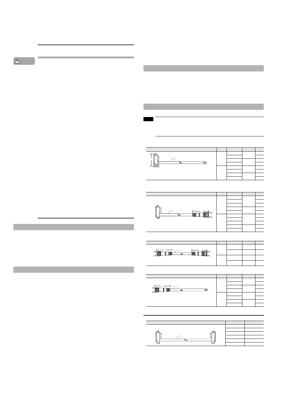
Junction cable
■
Extension cable
Series connection cable
Testing and maintenance
Standards and regulations
Danger
Checking the Package Contents
Cables
Shape
Type
Model
Output type
Length
Simple
function
SL-VP7P
PNP
7 m
SL-VP15P
15 m
SL-VP7N
NPN
7 m
SL-VP15N
15 m
Multi-
function
SL-VP7PM
PNP
7 m
SL-VP15PM
15 m
SL-VP7NM
NPN
7 m
SL-VP15NM
15 m
Shape
Type
Model
Output type
Length
Simple
function
SL-VPC03P
PNP
0.3 m
SL-VPC5P
5 m
SL-VPC10P
10 m
SL-VPC03N
NPN
0.3 m
SL-VPC5N
5 m
Multi-
function
SL-VPC03PM
PNP
0.3 m
SL-VPC5PM
5 m
SL-VPC10PM
10 m
SL-VPC03NM
NPN
0.3 m
SL-VPC5NM
5 m
Shape
Type
Model
Output type
Length
Simple
function
SL-VCC10P
PNP
10 m
SL-VCC10N
NPN
10 m
Multi-
function
SL-VCC10PM
PNP
10 m
SL-VCC10NM
NPN
10 m
Shape
Type
Model
Output type
Length
Simple
function
SL-VC5P
PNP
5 m
SL-VC10P
10 m
SL-VC5N
NPN
5 m
SL-VC10N
10 m
Multi-
function
SL-VC5PM
PNP
5 m
SL-VC10PM
10 m
SL-VC5NM
NPN
5 m
SL-VC10NM
10 m
Shape
Model
Length
SL-VS0
0.08 m
SL-VS01
0.15 m
SL-VS05
0.5 m
SL-VS1
1 m
SL-VS3
3 m
SL-VS10
10 m
SL-VHS transmitter x1
SL-VHS receiver
x1
Instruction Manual (this document) x1
Test piece x1
(Test piece with diameter of 25 mm and length of 200 mm)
Ferrite core x1
NOTE
5.8
36.1
14.3
φ
8-wire shielded cable
Brown and blue: AWG24 (nominal cross-sectional area of 0.22 mm
2
)
Others: AWG26 (nominal cross-sectional area of 0.14 mm
2
)
(Transmitter/receiver set)
45
17
5.8
φ
φ
(Transmitter/receiver set)
M14 connector, male*
* The simple function type has the M12 male connector.
44
17
17
45
φ
φ
5.8
φ
(Transmitter/receiver set)
M14 connector, male
*2
M14 connector, female
*1
*1 The simple function type has the M12 female connector.
*2 The simple function type has the M12 male connector.
44
17
φ
5.8
φ
(Transmitter/receiver set)
M14 connector, female*
Brown and blue: AWG24 (nominal cross-sectional area of 0.22 mm
2
)
Others: AWG26 (nominal cross-sectional area of 0.14 mm
2
)
* The simple function type has the M12 female connector.
5.8
φ
(Transmitter/receiver set)