Examples of wiring, External dimensions diagram, Specifications – KEYENCE SL-T11R User Manual
Page 5: Time chart, Fsd when edm input is used, Output connector b output connector a
5
SL-T11R-IM-E
Relay output terminal
Signal input/output terminal (In manual reset mode)
F1, F2
: Fuse
K3, K4
: External device (Magnet contactor, etc.)
S1
: The switch for reset input (N.O.)
S2
: The switch for wait input (N.O.)
S3
: The switch for override input (N.O.)
L1
: Muting lamp (Incandescent lamp or LED lamp)
P1, P2
: Muting device
(PZ self-contained photoelectric sensors
M
: 3-phase motor
PLC
: For the monitoring use. This is a NON SAFETY-RELATED system.
S2 and PLC are NON SAFETY-RELATED systems.
*1 No. 6 and No. 7 do not need to be wired when the SL-U2 is connected.
*2 If it is not necessary to perform error detection for K3 and K4 (when EDM input is not used), keep
the short bar between No. 8 and No. 9 connected.
*3 In the auto reset mode, keep the short bar between No. 10 and No. 11 connected. To release the
lockout condition of the SL-V through the reset input, connect the N.C. switch.
*4 The AUX output operates in the same way for both the signal input/output terminal and the output
connector B.
*5 For screw terminal 14 on the signal input/output terminal, the max load is 80mA. Because of this, a
muting lamp must be connected to another power source if the rated power consumption is greater
than 2W.
*1 For the specifications for the outputs other than FSD and for each input, refer to the SL-V Instruc-
tion Manual.
The followings are the response times for the combination between SL-V series and SL-T11R.
A) Maximum response time when the FSD goes to OFF state after the SL-V series detects inter-
ruption in the detection zone.
The response time (ON to OFF) for the SL-V series connected to SL-T11R + 6.0 ms
B) Maximum response time when the FSD goes back to ON state after the SL-V series detects no
interruption in the detection zone.
The response time (OFF to ON) for the SL-V series connected to SL-T11R + 15.0 ms
For your reference, see the instruction manual for SL-V series or user’s manual for SL-V
series (Chapter 7-3) to check the response time for SL-V series
The following are examples of total response times in cases where the SL-T11R is connected to
the SL-V series with the series-connection cable.
When connecting the SL-V32H (32 beam axes), SL-V24H (24 beam axes), and SL-V12L
(12 beam axes) in series, the response time of each unit is 10.3 ms, 9.2 ms, and 7.6 ms respectively,
and the response time (ON to OFF) is 10.3 ms+9.2 ms+7.6 ms+6 ms=33.1 ms
the response time (OFF to ON) is 10.3 ms+9.2 ms+7.6 ms+40 ms+15 ms=82.1 ms
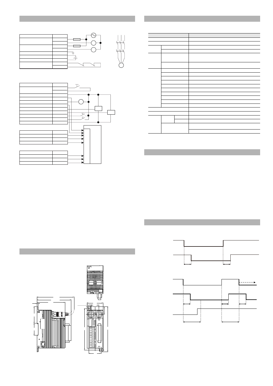
FSD
When EDM input is used
(1)
If the SL-V detects the operation of external device within the specified period of time (0.3 s) after
the operation of OSSD (ON to OFF, or OFF to ON), the normal operation continues.
(2)
Unless the SL-V detects the operation of external device within the specified period of time (0.3 s)
after the operation of OSSD (ON to OFF, OFF to ON), the SL-V goes to lockout condition due to an
EDM error.
Examples of Wiring
External Dimensions Diagram
K3
K3
F1
F2
K4
K3
K4
M
K4
Name
Terminal No.
FSD1
1
2
FSD2
3
4
FG
5
0V
*1
6
+24V
*1
7
EDM input
*2
8
9
PLC
IN
P1
L1
S2
S3
P2
S1
Black
Name
Terminal No.
Reset input
*3
10
11
+24V
12
AUX (auxiliary) output
*4
13
Muting lamp output
14
Clear/blocked output
15
Muting input 1
16
Muting input 2
17
Wait input
18
Override input
19
0V
21
Name
Pin No.
Interlock-reset-ready output
A-1
Alert output
A-2
0V
A-3
Name
Pin No.
AUX (auxiliary) output
*4
B-1
State information output 1
B-2
State information output 1
B-3
Output connector B
Output connector A
Black
Brown
Blue
Brown
Blue
*5
124
37
23
23
48
11
2-ø4.2
135
3.5
(102.3)
(112)
49.8
35.9
83.8
Specifications
Model
SL-T11R
Combined light curtain
SL-V Series
Response time FSD1, 2
ON to OFF: 6 ms OFF to ON: 15 ms
Rating
Power voltage
24 V DC
r10% (Ripple P-P 10% or less), Class2
Current consumption
100 mA or less (at 24V DC, SL-T11R alone)
Output
FSD1, 2
230 V AC, 4 A 30 V DC, 2 A (Resistance load)
230 V AC, 2 A (COS
I=0.3) (Inductive load)
30 V DC, 1 A (COS
I=0.3) (Inductive load)
Lifespan
Mechanical life: 10 million cycles or more
Electrical life: 0.1 million cycles or more
Environmental
resistance
Enclosure protection
IP20 (IEC60529) Set inside the control panel with IP54 or more
Pollution degree
2
Overvoltage category
III
Ambient temperature
-10 to +55
q
C (No freezing)
Storage ambient temperature
-25 to +60
q
C (No freezing)
Relative humidity
15 to 85% RH (No condensation)
Storage relative humidity
15 to 95% RH
Elevation
2000 m or less
Vibration
10 to 55 Hz, 0.7 mm compound amplitude, 20 sweeps each in X, Y, and Z directions
Shock
100 m/s
2
(Approx. 10 G) 16 ms pulse, in X, Y, Z directions 1,000 times each axis
Material
Polycarbonate
Weight
Approx. 330g
Approved
standards
EMC
EMS
EN61496-1, UL61496-1, IEC61496-1
EMI
EN55011 ClassA, FCC Part15B ClassA, ICES-003 ClassA
Safety
EN61496-1, UL61496-1, IEC61496-1 (Type 4 ESPE),
ISO 13849-1:2006 (Cat4 PL e)
UL508, EN50178
Response Time for Combination Between SL-V Series and SL-T11R
Time Chart
ON
OFF
ON
OFF
OSSD of SL-V
FSD
6ms
15ms
ON
(1)
(2)
OFF
ON
OFF
ON
OFF
Specified
period of time
0.3 s
Lockout condition
OSSD of SL-V
FSD
EDM input
6ms
15ms
6ms
Specified
period of time
0.3 s