Checking the package contents, Cable, Cable specification – KEYENCE SL-T11R User Manual
Page 2: Part names, Danger, Sl-t11r-im-e, Front view, Cable specification part names
2
SL-T11R-IM-E
1
The SL-T11R is a safety component as established by the EU Machinery Directive (2006/42/EC)
Annex V. The SL-T11R complies with the following EU Directives and EN Standards and has been
certified by TÜV SÜD Product Service GmbH.
EU Directives
• Machinery Directive (2006/42/EC)
• EMC Directive (2004/108/EC)
EN Standards
• EN61496-1 Type 4 ESPE
• EN55011 ClassA
• EN50178
2
The SL-T11R complies with the following IEC Standards and has been certified by TÜV SÜD
Product Service GmbH.
• IEC61496-1
Type 4 ESPE
• ISO13849-1:2006
Category4, PL e
3
The SL-T11R complies with the following UL (Underwriters Laboratories Inc.) and has been certi-
fied by UL. (CCN :NIPF/NIPF7)
• UL61496-1 Type 4 ESPE
• UL508
4
The SL-T11R also complies with the following EMI regulations in North America.
• FCC Part 15B
Class A Digital Device
• ICES-003
Class A Digital Apparatus
5
The SL-T11R has not obtained the model certification examination in accordance with Article 44-2
of the Japanese Industrial Safety and Health Law. Therefore, the SL-T11R cannot be used in Japan
as a "Safety Devices for Presses and Shearing Machines" as established in Article 42 of that law.
6
The SL-T11R has been designed in consideration of the following standards and regulations.
For details regarding the following standards, contact the third-party certification organization,
such as UL.
Corresponding standards
• EN60204-1
• EN692
• EN693
• OSHA 29 CFR 1910.212
• OSHA 29 CFR 1910.217
• ANSI B11.1 - B.11.19
• ANSI/RIA R15.06 - 1999
• SEMI S2
• "Guidelines for Comprehensive Safety Standards of Machinery", July 31, 2007, number
0731001 issued by Ministry of Health, Labor, and Welfare in Japan.
SL-T11R
u1
Instruction Manual (this document)
u1
Be sure to use the following cables for the connection between the SL-V and the SL-T11R.
The SL-T11R does not operate when combined with other SL-V cables.
n
Unit connection cable.
n
Junction cable
M14 connector male pin assignment
M14 connector female pin assignment
(1) Cable length
When using the unit connection cable and the junction cable together, the sum of the combined
cable length must not be 30 m or less for the transmitter and receiver respectively.
• Cables must be within the lengths specified. Failure to follow this specification may cause
improper operation of safety function, and may cause dangerous situation.
(2) Minimum cable bending radius : 5 mm (10 mm for the part where the connector to the SL-T11R is
attached)
(3) Identification of connector cables
Cables can be identified by the colors of their connectors and their cable insulation.
1. Cable Insulation colors
Cables for Transmitter : Cable insulation in grey
Cables for Receiver
: Cable insulation in black
2. Connector colors
Black connectors
Be sure to connect the unit connection cable for receiver to the SL-V receiver and the unit connection
cable for transmitter to the SL-V transmitter.
Standards and Regulations
Checking the Package Contents
Cable
Shape
Model
Length
SL-VPT3PM
3m
SL-VPT5PM
5m
SL-VPT10PM
10 m
Shape
Model
Length
SL-VCT10PM
10 m
Transmitter
Receiver
Pin No.
Wire color
Assigned function
Pin No.
Wire color
Assigned function
1
Pink
Interlock mode selection input
1
White
OSSD 2
2
Blue
0 V
2
Blue
0V
3
Violet
Wait input
3
Black
OSSD 1
4
Green
Interlock-reset-ready output
4
Yellow
RESET input
5
Orange
Communication cable 1
(RS485_+)
5
Orange
Communication cable 1
(RS485_+)
6
Orange/
Black
Communication cable 2
(RS485_-)
6
Orange/
Black
Communication cable 2
(RS485_-)
7
Brown
+24 V
7
Brown
+24 V
8
Red
AUX (auxiliary) output
8
Red
EDM input
9
Grey
State infromation output 1
9
Red/Black
Override input
10
Grey/Black
State infromation output 2
10
Yellow/
Black
Muting lamp output
11
Pink/Black
Alert output
11
Light blue
Muting input 1
12
White/
Black
Clear/Blocked Output
12
Light blue/
Black
Muting input 2
NOTE
5.8
17
45
36.1
14.3
(Transmitter/receiver set)
M14 connector, male
44
17
17
45
5.8
(Transmitter/receiver set)
M14 connector, male
M14 connector, female
Reference
Cable Specification
Part Names
Danger
1. Cable insulation
2. Connector
NOTE
See Instruction Man
ual.
T R
T R
POWER
FSD-ON
FSD-OFF
INTERLOCK
MUTE1
RESET
WAIT
EDM
O-RIDE
MUTE2
CAUTION
Electric shock
POWER
FSD-ON
FSD-OFF
INTERLOCK
MUTE1
RESET
WAIT
EDM
O-RIDE
MUTE2
CAUTION
Electric shock
See Instruction Man
ual.
1
2
3
4
5
6
7
8
9
1
2
3
4
5
6
7
8
9
10
11
12
13
14
15 16 17
18
19
20
21
10
11
12
13
14
15 16 17
18
19
20
21
MODE SWITCH
1 MANUAL RESET
2 AUTO RESET
3 not use
4 not use
5 not use
6 not use
7 not use
8 not use
A-1 A-2 A-3
B-1 B-2 B-3
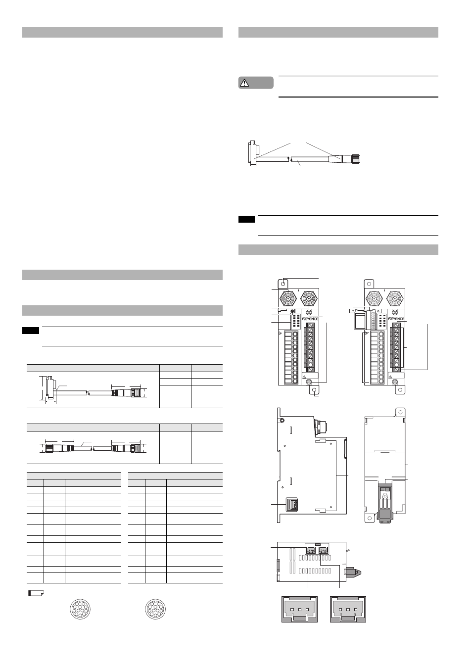
SL-V Series connector,
"T" side
SL-V Series connector,
"R" side
Mode switch
cover fastener
Front view
Front view
Side
Rear
Output connector A Output connector B
Bottom
Indicators
SL-U2 connector
*Covered by tape at
time of shipment.
Signal input/output
terminal block
Mode switches
Relay circuit board
replacement screw
Hole for mounting screw
(for M4)
SL-U2,
mounting
holes
DIN rail
mating area
Terminal
replacement
screws
Hole for mounting screw (for M4)
Din rail
lock pin
Relay output
terminal block
Connector for the
light interference
prevention connection
*Covered by tape at
time of shipment.