Mode switch, Connection terminal assignment, Indicators – KEYENCE SL-T11R User Manual
Page 3: Din rail mounting, Screw mounting, Note on installation, Sl-t11r-im-e, Relay output terminal signal input/output terminal, Output connector a output connector b, Din rail removal method
3
SL-T11R-IM-E
* Default
Relay output terminal
Signal input/output terminal
*1 When using the muting bank function in SL-V Series Ver. 3, terminal no. 18
switches to muting bank input 1, and terminal no. 19 switches to muting bank
input 2. In addition, when both Mode Switch 1 and 2 are turned OFF, terminal no.
20 switches to muting bank input 3.
For information about the Muting function, please refer to the SL-V Series Instruction Manual.
Short bars are attached for the purpose of connection between No.8 and No.9, and between No.10 and
No.11. Each short bar has a different length respectively. When reconnecting them after removal, make
sure to connect the correct short bar.
Output connector A
Output connector B
1
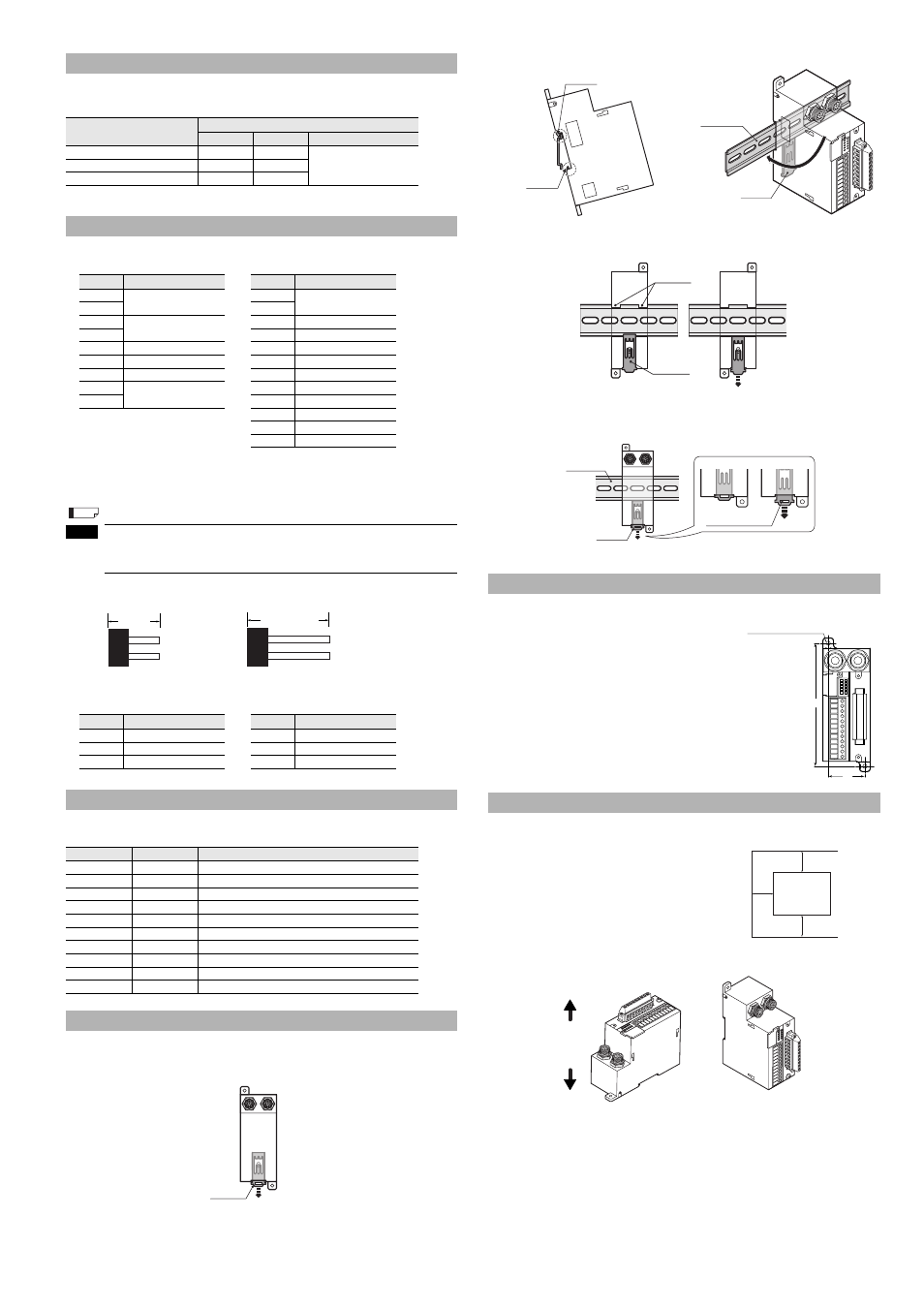
Push hook B down with a screwdriver to release the lock mechanism.
2
3
4
DIN Rail Removal Method
The two mounting holes are used to install the SL-T11R with two
M4 screws.
(Recommended tightening torque: 0.7 N m)
Always leave at least 30 mm of open space between the SL-R11 and other equipment or walls.
* When using the SL-U2, position the SL-U2 at least 30 mm from the edge of the cabinet.
Install the SL-R11 in one of the following two orientations:
Mode Switch
Mode
Switch No.
1
2
3 to 8
Auto Reset*
OFF
ON
Not used (Always OFF)
Manual Reset
ON
OFF
I/O Monitoring Mode
OFF
OFF
Connection Terminal Assignment
Terminal No.
Name
Terminal No.
Name
1
FSD1
10
Reset input
2
11
3
FSD2
12
+24V
4
13
AUX (auxiliary) output
5
Function ground
14
Muting lamp output
6
0V
15
Clear/blocked output
7
+24V
16
Muting input 1
8
EDM input
17
Muting input 2
9
18*
1
Wait input
19*
1
Override input
20*
1
Not used
21
0V
Terminal No.
Name
Terminal No.
Name
A-1
Interlock-reset-ready output
B-1
AUX (auxiliary) output
A-2
Alert output
B-2
State information output 1
A-3
0V
B-3
State information output 2
Indicators
Name
Light color
Description
POWER
Green
Lights when power is supplied
FSD ON
Green
Lights when FSD turns ON
FSD OFF
Red
Lights when FSD turns OFF
INTERLOCK
Yellow
Lights when in interlock condition
MUTE 1
Orange
Lights when muting input 1 turns ON
MUTE 2
Orange
Lights when muting input 2 turns ON
RESET
Orange
Lights when reset input turns ON
WAIT
Orange
Lights when wait input turns ON
EDM
Orange
Lights when EDM input turns ON
O-RIDE
Orange
Lights when override input turns ON
DIN Rail Mounting
Reference
NOTE
Approx.
19 mm
Approx. 23 mm
Short bar for connection
between No.8 and No.9
Short bar for connection
between No.10 and No.11
(Front View)
Hook B
Screw Mounting
Note on Installation
Hook A
Hook B
* Hook A latches
on DIN rail
DIN rail
Hook B
* Push controller until
hook B latches.
[Locked state]
[Unlocked state]
Hook B
Hook A
* Position hook B so that it is locked.
(Front View)
DIN rail
Hook B
Push down using
a screwdriver.
124
37
2-
I4.2 (mounting hole)
SL-T11R
30mm
30mm
30mm
Ceiling
Floor