Connection to the sl-u2 recommended power supply, Connection to the sl-v, Wiring the relay output terminal – KEYENCE SL-T11R User Manual
Page 4: Wiring the signal input/output terminal, Wiring output connectors a and b, Replacing the relay board, Internal circuit diagram, Sl-t11r-im-e
4
SL-T11R-IM-E
The power can be supplied from the SL-U2 dedicated power supply by connecting it to the SL-T11R
via the connector on the side of the SL-T11R.
1 Remove the seal that is attached for protecting the connector.
2 For DIN rail mounting
• Mount the SL-T11R and the SL-U2 to the DIN rail, and slide either one to couple the con-
nectors.
For screw mounting
• Couple the connector according to the figure above.
3 Slide the SL-U2 connection hook to fasten it to the SL-T11R.
•
• Tightening torque 4.4 lb
in (0.5 Nm)
• Wire rating
AWG # 22 to 12 (Stranded only, Copper only, min. 60
qC)
• Cable stripping dimension
• Tightening torque 4.4 lb in (0.5 N m)
• Wire rating
AWG #22 to 14 (Stranded only, Copper only, min. 60
qC)
• Cable stripping dimension
When wiring output connectors A and B, prepare the following connectors and cable.
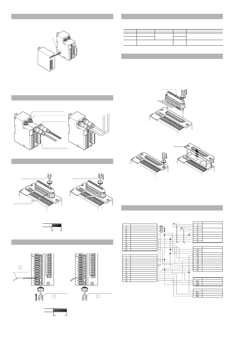
The relay used for the FSD of the SL-T11R can be replaced without rewiring the connection terminal.
1
Prepare the relay board for the SL-T11R (OP-84388).
2
Turn off the power to the SL-T11R and all the devices connected to the SL-T11R.
3
Loosen the two terminal replacement screws, and remove the relay output terminal.
4
Remove the current relay board for the SL-T11R from the SL-T11R.
5
Install the new relay board for the SL-T11R to the SL-T11R, and tighten the terminal
replacement screws. (Recommended tightening torque: 0.6 N m)
6
Install the relay output terminal to the relay board for the SL-T11R. (Recommended
tightening torque: 0.4 N m)
7
Check the operation according to the checklist.
For the internal circuit of the SL-V, refer to the SL-V Instruction Manual.
Connection to the SL-U2 Recommended Power Supply
Connection to the SL-V
Wiring the Relay Output Terminal
Wiring the Signal Input/Output Terminal
* Install while
being careful of
the connectors
Connector for Receiver (black)
Connector for transmitter (grey)
Receiver cable
(Cable insulation of black)
Transmitter cable
(Cable insulation of grey)
Insert wire
Loosen with flat-head
screwdriver.
Tighten with flat-head
screwdriver.
7mm
See Instruction Man
ual.
See Instruction Man
ual.
2
1
3
Insert wire
Loosen with flat-head
screwdriver
Tighten with flat-head
screwdriver
10mm
Wiring Output Connectors A and B
Name
Model
Manufacturer
Quantity
Notes
Connector
DF1E-3S-2.5C
HIROSE
ELECTRIC CO., LTD.
2
KEYENCE also offers OP-42365 as an option
(set of 2 connectors and 6 crimp terminals).
Crimp terminal
DF1B-2022SC
6
Cable
6-core cable
AWG #20 to 22
1 (30 m or less)
Supplied by customer.
Replacing the Relay Board
Internal Circuit Diagram
Relay output terminal
Relay board for the SL-T11R
Output connector B
Output connector A
Signal input/output terminal
Relay output terminal
Connector cable for transmitter
Connector cable for receiver
Pin No.
Name
OSSD2
0V
OSSD1
Reset input
Communication cable 1 (RS485+)
Communication cable 2 (RS485-)
+24V
EDM input
Override input
Muting lamp output
Muting input 1
Muting input 2
Pin No.
Name
Interlock mode selection input
0V
Wait input
Interlock-reset-ready output
Communication cable 1 (RS485+)
Communication cable 2 (RS485-)
+24V
AUX (auxiliary) output
State information output 1
State information output 2
Alert output
Clear/blocked output
Terminal No.
Name
FSD1
FSD2
Function ground
0V
+24V
EDM input
Terminal No.
Name
Reset input
+24V
AUX (auxiliary) output
Muting lamp output
Clear/blocked output
Muting input 1
Muting input 2
Wait input
Override input
0V
Pin No.
Name
Interlock-reset-ready output
Alert output
0V
Pin No.
Name
AUX (auxiliary) output
State information output 1
State information output 2