Doepfer Wheel Electronic User Manual
Page 9
User's Guide
Wheel Electronic V1.0
Page 9
In both cases an additional 10k resistor is required (possible range 4k7 to 100k) to pull the
analog input to a defined state during the switch is open.
• Version 1: The resistor is soldered between GND and the measuring input . This way the
input is pulled to GND ( =0V corresponding to Midi data 0) as long as the switch is left open.
When the switch is closed the voltage jumps to +5V corresponding to Midi data 127.
• Version 2: The resistor is soldered between +5V and the measuring input . This way the
input is pulled to +5V (corresponding to Midi data 127) as long as the switch is left open.
When the switch is closed the voltage jumps to 0V corresponding to Midi data 0.
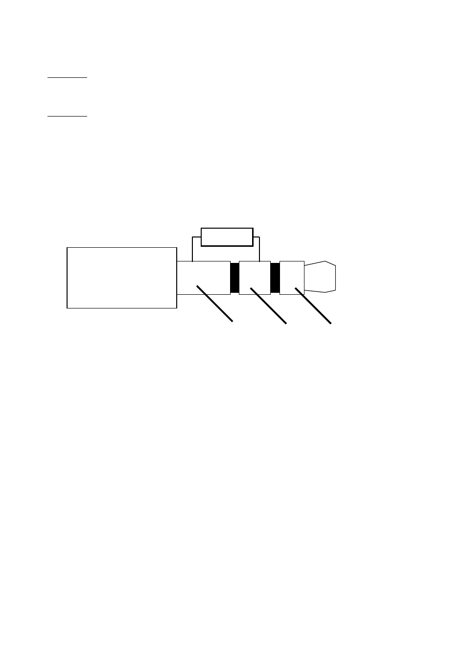
Even a Yamaha breath controller BC-1/2/3 can be connected to connector ST4 if preset #2 is
used (please refer to page 11). The stereo miniature plug of the BC-1/2/3 uses the same signals
as ST4 of WE: GND, control voltage and +5V. In addition a pull-up resistor (about 1k ...4k7) has
to be added between the control voltage pin and +5V. This measure is – at least for the BC-2 –
required as a serial diode is added to the breath controller's output. Then BC2 generates a
voltage in the range of +5V (no pressure) to ~ +2,5V (maximum pressure). In addition the
behaviour can be adjusted by the trimming potentiometers offset and gain of the BC2.
The pinout of the breath controller connector is taken from the service manual of Yamaha BC2.
Pay attention to the unusual connection of +5V and GND ! A BC2 has been tested successfully
in combination with WE. The specification of the breath control connector is without obligation
for other devices! Please check if the connector of your breath control is identical. We are not
responsible for defective breath controllers connected in the wrong way. We recommend the
usage of a 3,5 mm stereo jack socket for the connection. The socket is connected to ST4 of WE
via the 3-pin cable set that is included with WE.
Connector for the switching control (6)
The switching control (e.g. a foot switch or any other switch) is connected to the two pins of
ST5. The polarity for the switch is adjusted by means of the jumper JP2-5. If the foot switch
behaves in the opposite way as expected simply change the setting of JP2-5. For details please
refer to the chapter Function of the jumper area JP2
We recommed the usage of two-pin cable set with suitable female connector to establish the
connection between WE and the switching control. In this way the controls might be
disconnected from the electronics very easily.
+5V
control
voltage
GND
~ 3k3