Doepfer Wheel Electronic User Manual
Page 10
Page 10
Wheel Electronic V1.0
User's Guide
Controls and Operation
In addition to the elements connected to ST1…ST5 WE has these controls available:
•
Jumper area JP1 for adjustment of Midi channel and preset selection
•
Jumper area JP2 for voltage range selection and polarity of the foot switch
•
Trimming potentiometer P1 for adjustment of the reduced voltage range +V
Function of the jumper area JP1
The jumper area JP1 is made of a double row pin header with 16 pins that can be used to install
up to 8 jumpers. The jumpers 1…4 are used to adjust the Midi channel. With the jumpers 5…8
one of the presets is selected. A preset defines the assignments of Midi messages to the analog
inputs ST1…ST4 and the switching input ST5.
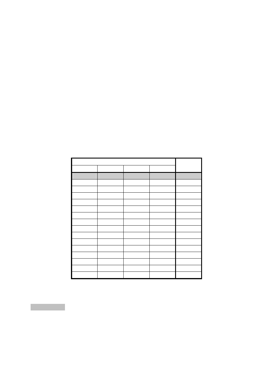
The following table shows the relation between the settings of the jumpers 1…4 of JP1 and the
corresponding Midi channels:
Jumper #
1 2 3 4
Midi-
channel
5
1
2
3
4
5
6
7
8
9
10
11
12
13
14
15
16
5 = jumper installed
The factory setting is shaded grey (Midi channel 1).
- DIY Synth do-it-yourself analog synthesizer (24 pages)
- MKE Universal Midi Keyboard Electronics Kit (17 pages)
- CTM64 Contact to Midi Interface (main board) (20 pages)
- CTM64 Relay Board (8 pages)
- MTC64 Midi to Gate Interface (main board) (16 pages)
- MTC64 Relay Board (8 pages)
- MTC64 Output Board (transistor driver board) (4 pages)
- MTC64 Power Board (8 pages)
- Pocket Electronic (32 pages)
- Dial Electronic (12 pages)
- USB64 Universal Midi and USB Controller Electronics Kit (20 pages)
- MBP25 Midi Bass Pedal Electronics Kit (16 pages)
- MTV16 Midi-to-Voltage Interface with 16 Analog Voltage Outputs (8 pages)
- A-100 (8 pages)
- A-100AD5 +5V low cost adapter (46 pages)
- A-100(~ 40 MB) (744 pages)
- A-100CGK CV/Gate keyboard (12 pages)
- A-101-1 Vactrol Steiner Filter (6 pages)
- A-101-2 Vactrol Lowpass Gate (6 pages)
- A-101-3 Vactrol Modular Phase Filter (10 pages)
- A-101-9 Universal Vactrol Module (14 pages)
- A-102 Diode Low Pass (6 pages)
- A-104 four-fold Trautonium Formant Filter (6 pages)
- A-105 24dB SSM Low Pass (8 pages)
- A-106-1 Xtreme Lowpass/Highpass Filter (12 pages)
- A-107 Multitype Morphing Filter (18 pages)
- A-108 6/12/24/48 Formant Filter (10 pages)
- A-109 Voltage Controlled Audio Signal Processor (10 pages)
- A-110 Standard VCO (12 pages)
- A-111-1 High End VCO (14 pages)
- A-111-5 Synthesizer Voice (22 pages)
- A-112 Sampler/Wavetable Oscillator (24 pages)
- A-113 Subharmonic Oscillator (14 pages)
- A-114 Dual Ringmodulator (6 pages)
- A-115 Audio Divider (6 pages)
- A-116 VC Waveform Processor (6 pages)
- A-117 Digital Noise / 808 Source (8 pages)
- A-118 Noise/Random (6 pages)
- A-119 External Input/Envelope Follower (8 pages)
- A-120 24dB Low Pass 1 (8 pages)
- A-121 12dB Multimode VCF (10 pages)
- A-123 24dB High Pass (no longer available) (8 pages)
- A-124 Wasp Filter (8 pages)
- A-125 VC Phaser (8 pages)