Doepfer Wheel Electronic User Manual
Page 16
Page 16
Wheel Electronic V1.0
User's Guide
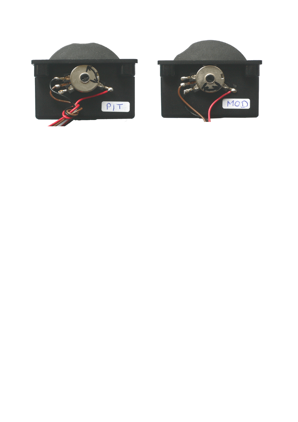
Pictures of the wired wheel box
Both potentiometers have to be turned into the correct positions because the potentiometers may be
mounted at different positions from the factory. There are two possibilities:
• Unscrewing the nut that holds the potentiometer by means of a suitable screw wrench – rotating the
potentiometer into the correct position – fixing the nut
• Pulling the wheel off the potentiometer axis and achse and installing the wheel at the correct position
The correct position can be found by moving the wheel to the lowest position. Then the potentiometer
has to be rotated that just the Midi data 0 is sent. As soon as the wheel is moved Midi data > 0 have to
be send (without much dead zone – otherwise the potentiometer has to be readjusted again). Then the
trimming potentiometer of the Wheel Electronic is adjusted so that with the wheel in the upper position
Midi data 127 is sent (again with not too much dead zone). For the pitch-bend wheel in addition the
center position has to be checked. In the neutral position of the wheel Midi data 64 has to be sent.
Otherwise the position of the potentiometer and/or the trimming potentiometer setting has to be
corrected again. The adjustment is correct if 64 is sent in the center position, 0 is reached at the lowest
position of the wheel and 127 in the upper position of the wheel.