Doepfer Wheel Electronic User Manual
Page 8
Page 8
Wheel Electronic V1.0
User's Guide
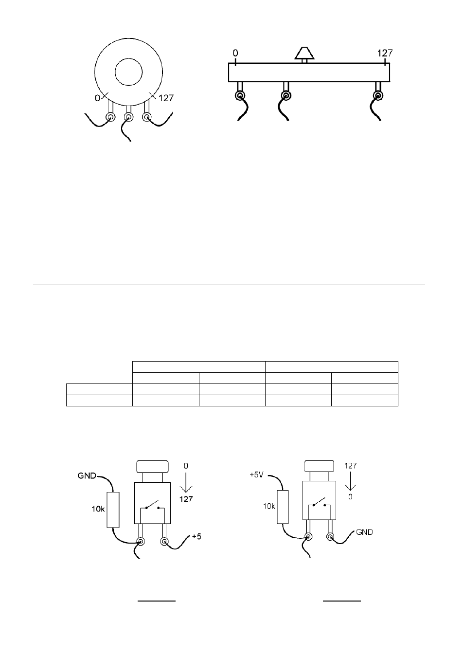
Connection of a momentary or
toggle switch (version 1)
Connection of a momentary or
toggle switch (version 2)
Measuring input
Measuring input
Linear potentiometers with resistance values 4k7 ... 100k can be used. We recommend 10k
(linear).
Important: Unused measuring inputs have to be connected to GND or +5V. Avoid open inputs !
An open input will cause the transmission of random Midi data causing undesirable side effects
at the Midi receiver (e.g. Midi overflow or random parameter fluctuations). E.g. jumpers can be
used to connect the center pin of ST1…ST4 to GND (left position) or +5V (right position).
Even momentary or toggle switches can be connected to ST1…ST4 altought WE was not
developed for this application. The switches can be used in two different ways:
state of rest
active state
Midi
data voltage Midi
data voltage
version 1
0
0V
127
+5V
version 2
127
+5V
0
0V
Simple momentary switches (1 contact, open at rest) or simple toggle switches (1 contact
on/off) are required. According to the desired behaviour (version 1 or 2 in the above table) the
switch has to be wired correspondingly:
Connecting a rotary potentiometer
to ST1…ST4
(valid for potentiometers of
modulation wheels, foot controllers
and joysticks too)
Connecting a fader potentiometer
to ST1…ST4
measuring input
measuring input
+5V
GND
GND
+5V