Doepfer Wheel Electronic User Manual
Page 12
Page 12
Wheel Electronic V1.0
User's Guide
Control change # 1 is used for fast/slow, # 68 for on/off. Please refer to the B4 manual for
details. In addition volume and expression are available.
•
Preset # 5 is a special preset for joy sticks. Starting from the center position (i.e. about +2.5V
control voltage) for up/down and left/right movement of the joy stick different Midi control
changes are used (1/2, 3/4, 5/6 and 7/8).
•
Preset # 6 is a special preset for triple (or dual) foot controllers. For sustain one can choose
between the continuous version (ST1) or the switching version (ST5). In addition a volume
controller can be used. If a foot controler with switches is used the wiring for switches has to
be made (please refer to page 9). If a foot controller with potentiometers is used it depends
upon the type of potentiometer how it has to be wired. If potentiometers with three terminals
are used they are connected like normal potentiometers (please refer to page 8). If
potentiometers with only two terminals are used (variable resistor only) the two terminals
have to be connected to GND and the measuring input. In addition a pull-up resistor has to
be connected between the measuring input and +5V. One has to try out different values for
the resistor. Half the value of the potentiometer is a good starting point. Even a trimming
potentiometer instead of a fixed resistor can be used. If the behaviour is reverse the
connections have to be exchanged: pull-down resistor between GND and the measuring
input, potentiometer of the foot controller between the measuring input and +5V). Even foot
controllers with a combination of switches and potentiometers are available (e.g. the FATAR
VFP3-2D).
• Presets # 7 to 15 are not used in the first version of the WE firmare.
Function of the jumper area JP2
The jumper area JP2 consists of a double row pin header with 10 pins that can be used to install
up to 5 jumpers. Four jumpers are used to select between full voltage range (0…+5V) or
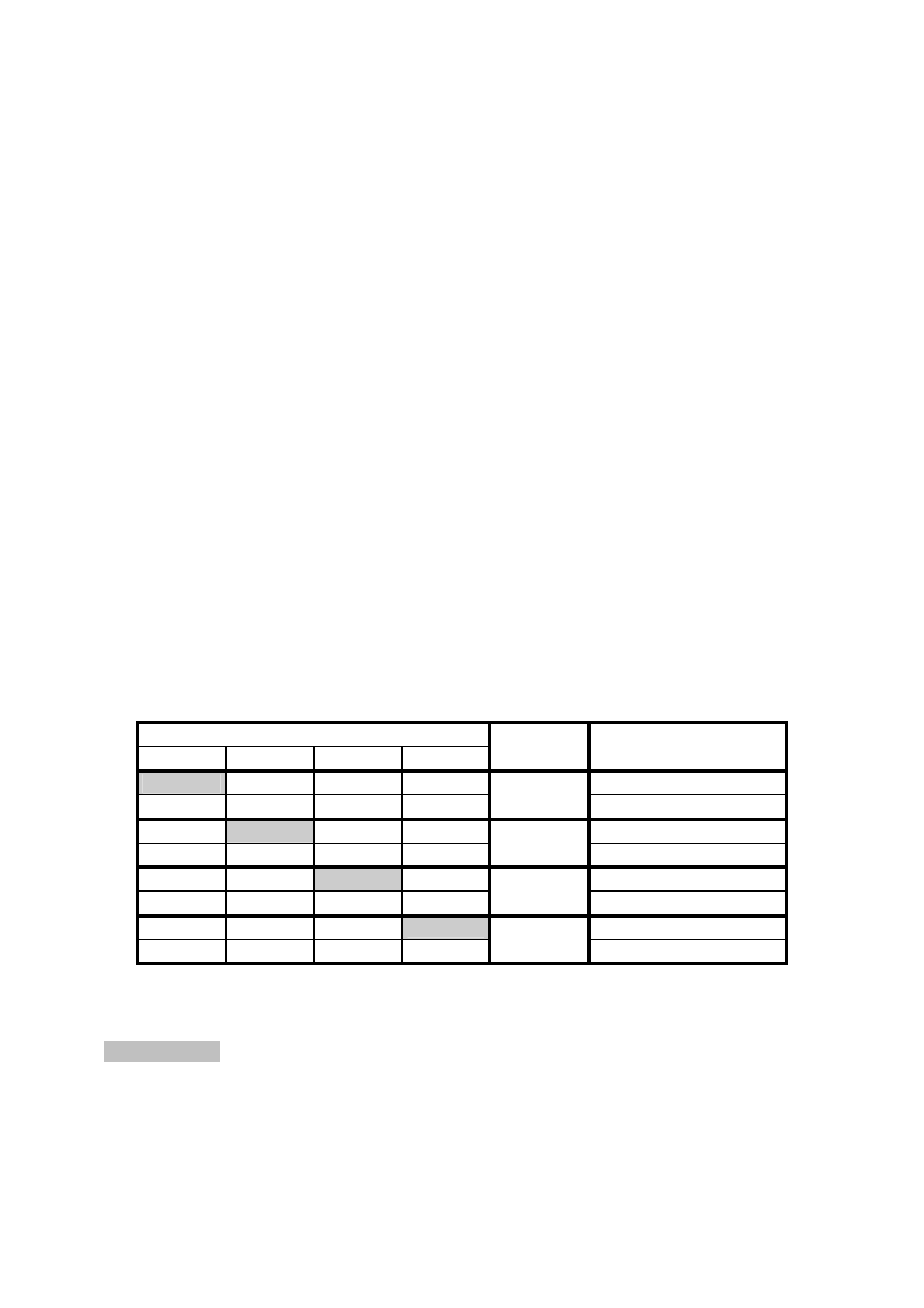
reduced voltage range (0…+V) for the analog inputs ST1…ST4. The following table shows the
relation between the settings of the jumpers of JP2 and the corresponding voltage ranges for
the analog inputs ST1…ST4:
Jumper
1 2 3 4
Input
Voltage range
0…+5V
-
ST1
0…+V
0…+5V
-
ST2
0…+V
0…+5V
-
ST3
0…+V
0…+5V
-
ST4
0…+V
= jumper installed
- = jumper not installed
The factory setting is shaded grey (all inputs full range 0...+5V).
The fifth jumper JP2-5 is used to adjust the polarity of the foot switch connected to ST5. If JP2-5
is installed the foot switch has to be closed-at-rest. If JP2-5 is not installed the foot switch has to
be open-at-rest. If the foot switch behaves in the opposite way as expected simply change the
setting of JP2-5. The factory setting is installed.