Mounting – Doepfer Wheel Electronic User Manual
Page 13
User's Guide
Wheel Electronic V1.0
Page 13
Function of the trimming potentiometer P1
The trimming potentiometer P1 is used to adjust the reduced voltage range V+. Any voltage
between 0V and +5V can be adjusted though only voltages in the range +3...+5V should be
used. Reference voltages below +3V cause malfunction of the analog-to-digital converters
though nothing can be damaged. The reduced voltage V+ becomes valid for an input if the
corresponding jumper of JP2 is removed (see above table).
For the adjustment of P1 a small screw driver is necessary. P1 is a multi-turn potentiometer to
enable a fine adjustment of V+. When P1 is turned counterclockwise (CCW) V+ increases,
clockwise (CW) V+ decreases. The factory setting is fully CCW (+5V). This is the same as if the
+5V range is selected by the corresponding jumper of JP2.
If the reduced voltage range V+ is required (e.g. for modulation wheels, foot controllers, some
joy sticks) the element connected to ST1...ST4 should be set to it's maximum position, i.e. the
position that corresponds to a Midi data value 127. Beginning from fully CCW P1 is adjusted so
that a Midi value a bit below 127 is sent (e.g. 125). Then P1 is re-adjusted a little bit until just
data 127 appears. If the element connected to ST1...ST4 does not transmit Midi data 0 in it's
minimum position the potentiometer inside the modulation wheel, foot controller or joy stick has
to be twisted until data 0 is send. After that P1 has to be readjusted again as described above.
A Midi monitor program is a very useful tool for the adjustment of P1, e.g. Midi Ox. A link to this
shareware program is available on our website.
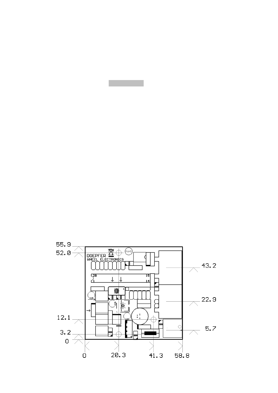
Mounting
Before WE is put into operation the board has to be fixed on a suitable support and built into a
metal case together with the controls (refer to EMC notes on page 2). The metal case has to be
connected to GND of WE. We recommend to use the metal plate of the voltage regulator
7805/IC3 or the GND terminal of the power supply socket for this connection.
The board measures about 59 x 56 x 25 mm. Three mounting holes with 3 mm diameter are
available for mounting the board inside the case e.g. with distance sleeves or spacers (> 5 mm
in length) and suitable screws. Pay attention that no short circuits are made – neither on the top
of the board (electronic parts) nor on the bottom (solder points or pcb tracks). In case of doubt
use isolating plastic parts (e.g. plastic screws, nuts and washers) for mounting.
Position of the mounting holes and sockets
(measures in mm)