Cub Cadet P Series User Manual
Page 29
24
PC Series
REMOVAL, INSPECTION AND/OR
REPLACEMENT OF CONTROL ARM
REMOVAL, INSPECTION AND/OR
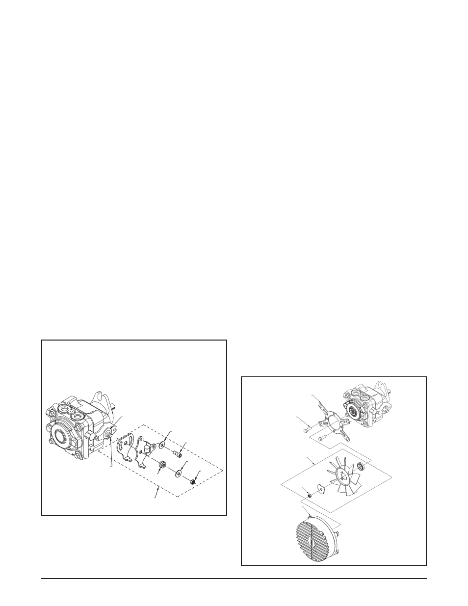
REPLACEMENT OF FAN ASSEMBLY
Refer to Figure 3.
Disassembly
1. Remove the fan shroud (210) from the mounting
bracket (209) by carefully pushing down on the
shroud tabs.
2. Remove the nut (106) and fan assembly (90).
3. Remove the bolts (10) and bracket (209).
Inspection
Inspect the fan shroud (210), fan assembly (90) and
mounting bracket (209) for damage.
Assembly
1. To install the mounting bracket (209), align and
insert the bolts (10) into the bracket and charge
pump cover. While holding the charge cover in
place, tighten the bolts (10) per table 2, page
22.
2. Install the fan and washer assembly onto the
shaft.
3. Install the nut (106) and tighten per table 2, page
22.
4. Install the fan shroud (210) onto the mounting
bracket (209). Make sure that all shroud lock
tabs are fully engaged in the mounting bracket
slots.
Figure 2. Standard Control Arm
Figure 3. Fan Assembly
Refer to Figure 2.
Disassembly
1. Remove the nut (106), washer (104) and bushing
(101).
2. Remove the outer control arm bracket.
3. Remove bolt (103), washer (104) and the inner
control arm bracket.
Inspection
1. With the arm control linkage removed, inspect
the trunnion arm (37) and trunnion arm seal (49).
2. Inspect bushing (101) and all other linkage parts
for damage, corrosion or wear.
Assembly
1. Install the inner control arm bracket, washer
(104) and bolt (103).
NOTE: Do not over tighten the bolt (103). The
bracket must move freely.
2. Install the outer control arm bracket, bushing
(101), washer (104) and nut (106). Tighten to
the correct torque value. See page 22.
49
37
101
110
104
103
104
106
209
(2X) 10
90
106
210