Graphical schematic – Cub Cadet P Series User Manual
Page 15
10
P Series
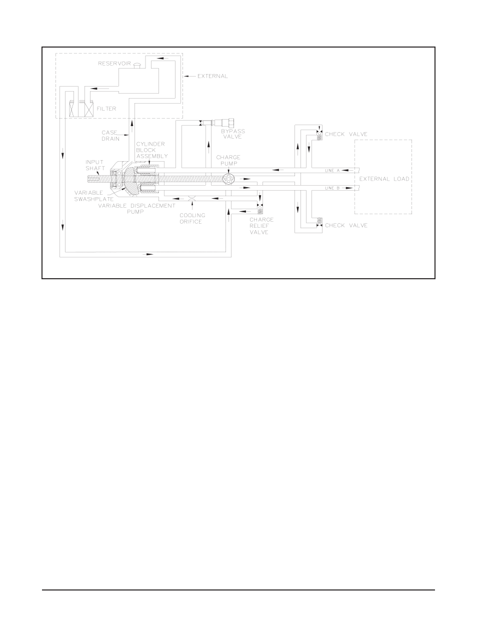
Figures 10 represents a graphical schematic of the
P Series Pump with standard charge pump. Figure
10 provides a graphical illustration of the hydraulic
oil circuit.
The input shaft and pump cylinder block are turned
in one direction only by the engine/drive belt/pulley
combination or direct drive gear box.
The oil is drawn through an external filter by the
charge pump. The filter prevents contaminants
within the reservoir from entering into the charge
pump gerotor.
The charge pump supplies fluid to keep the closed
loop pressurized, preventing cavitation and provid-
ing cooling oil flow for the system.
The charge relief valve is used to maintain charge
at a predetermined pressure.
Output of the system oil flow is controlled by the
direction and amount that the swashplate is
angled. As the pump pistons compress, they force
oil into one of two passageways (“A” or “B”) in the
system hydraulic circuit. Oil is supplied externally
under pressure to an external load, (e.g., a vehicle
wheel motor).
As the angle of the pump swashplate is increased,
the amount of oil being pumped will increase and
cause a higher speed output of the wheel motor.
Reversing the angle of the swashplate will reverse
the direction of the oil flow. During the operation
of the pump, fluid is “lost” from the hydraulic loop
through leak paths designed into the product for
lubrication and cooling purposes (around pistons,
under the rotating cylinder block, etc.). This “lost”
fluid returns to the reservoir through the case drain.
This fluid must be made up in the loop. The charge
pump makes up this fluid loss.
The makeup flow is controlled (or directed) by the
system check valves. The check valves are used
to direct makeup fluid into the low pressure side
of the closed loop. Each check valve will either be
held open or closed, depending upon the direction
of the vehicle operation: Closed in a pressurized
system passage, open in a low pressure, “charged”
system passage.
Figure 10. P Series Pump With Standard charge Pump
GraPHIcal ScHematIc