Cub Cadet P Series User Manual
Page 103
98
PR Series
Refer to Figure 9.
Disassembly
1. Prior to removal of the charge pump cover, place
a mark on the cover and end cap for alignment
at assembly.
2. Using a 1/2 inch wrench loosen the charge
pump cover bolts (56) from the end cap (2).
While holding the charge cover in place, remove
the charge cover bolts (56).
3. Remove the charge cover, O-ring (39) and
gerotor items (41). Carefully check for and
remove the charge spring and charge ball
(44).
4. For the Thru Shaft charge pump, remove the
shaft seal.
Inspection
1. Inspect the charge cover O-ring and running
surfaces for damage. Inspect the spring, check
ball (44), and mating seat in the end cap for
damage or foreign material.
Assembly
REMOVAL, INSPECTION AND
ASSEMBLY OF STANDARD OR
THRU SHAFT CHARGE PUMP
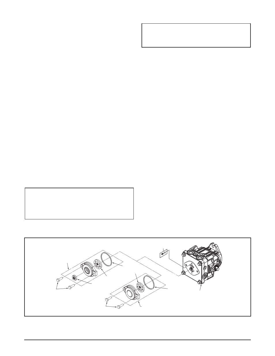
Figure 9. PR Pump Standard or Thru Shaft Charge Pump
NOTE: If the end cap (2) is to be re-
moved from the housing, do not as-
semble the charge pump (40) until the
end cap is installed on the housing.
2. Inspect the charge cover bore for damage,
corrosion or wear.
1. Lubricate the new shaft seal with petroleum
jelly.
2. Press the shaft seal into the charge cover. Be
careful not to damage the seal or charge cover
bore.
3. Position the pump with the input shaft down, and
the end cap (25) horizontal. Place the charge
ball (44) in the end cap (25) charge passage
so the ball mates to the end cap (25) charge
ball seat. Place the charge spring, on top of the
charge ball.
4. Insert the outer gerotor over input shaft.
5. Align the outer gerotor to fit over the inner
gerotor.
6. Insert the O-ring (39) into the groove in the
charge cover.
7. Position the charge cover and O-ring (39) with
the aligning mark on the end cap (25). Place the
charge cover and O-ring with aligning mark on
the end cap. Place the charge cover and O-ring
as one piece over the charge spring and gerotor
assembly. Insure the spring fits into the charge
cover spring retaining groove.
8. Align and insert the charge pump cover bolts
(56) into the end cap (25). Tighten to the correct
torque value. See Table 2, page 92. (Torque
Values.)
NOTE: For the Thru Shaft charge pump
follow steps 1-8. For the Standard charge
pump follow steps 3-8.
44
25
39
40
56
41
39
41
37
56
40
STANDARD
THRU SHAFT