Cub Cadet RZT-S Series User Manual
Page 80
RZT-S
74
5d.
Interpretation:
•
If the stator fails either or both tests, it is likely to be bad.
•
If the stator fails the output test, but passes the resistance test, there is a possibility that the magnets on
the rotor (flywheel) have lost their fields. This is theoretically possible, but extremely rare in practice.
•
It is necessary to remove the flywheel to test the magnets. If the magnets inside the flywheel will draw a
steel screwdriver to them, they are good. If not, the flywheel must be replaced.
6.
Regulator/rectifier check: See Figure 7.21.
6a.
Check the ground.
•
With the engine running and the stator leads re-
connected to the regulator/rectifier, perform a
ground-side voltage-drop test from the regulator/
rectifier to the engine block.
•
If the voltage reading is greater than 0.1 Volts
DC, replace or properly fasten the ground wire
that connects the regulator/rectifier to the engine
block. Retest to confirm good connection.
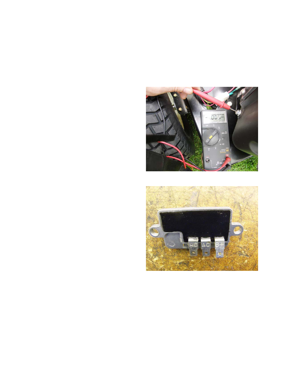
6b.
Bench Test: See Figure 7.22.
•
Set a digital multi-meter to read on the X100
Ω
scale.
•
With the key OFF and the fuse removed, unplug
all the wires from the regulator/rectifier.
•
Remove the regulator/rectifier from the engine
(not strictly necessary, but provides easy
access).
•
Make the resistance tests described in the
accompanying table.
•
B+ is the DC terminal
•
AC1 is the AC terminal nearest B+
•
AC2 is the AC terminal furthest from B+
Figure 7.21
Figure 7.22
AC2 AC1 B+