Charging circuit – Cub Cadet RZT-S Series User Manual
Page 77
Electrical System
71
Charging circuit
How it works
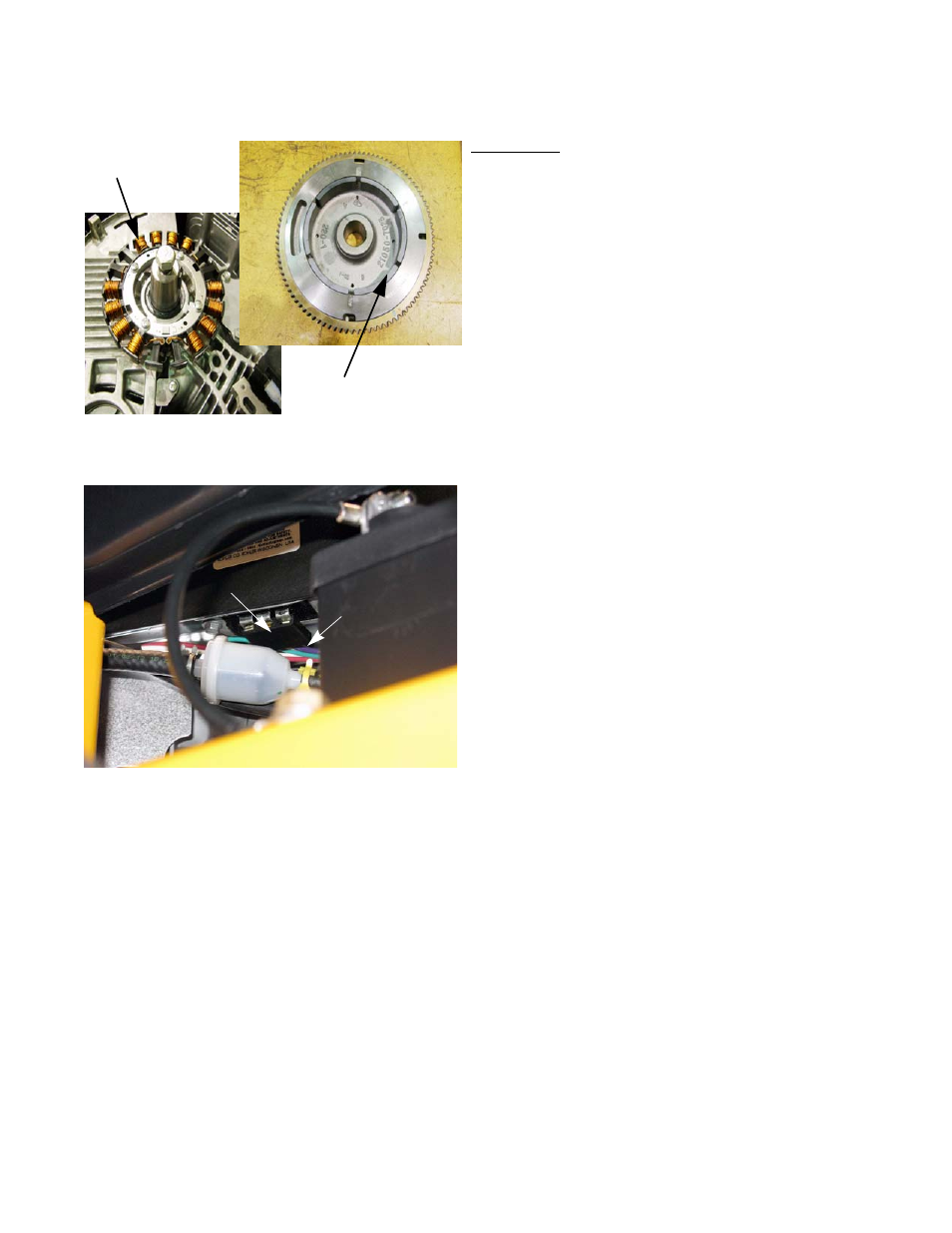
1. When the engine is running, magnets attached to the
underside of the flywheel induce AC (Alternating Cur-
rent) in the stator that is mounted beneath the fly-
wheel. See Figure 7.15.
2.
The AC travels from the stator to and from the regula-
tor/rectifier through the two white wires.
NOTE: The magnets inside the flywheel act as a rotor for
the charging system.
3.
The regulator/rectifier takes alternating current and
converts (rectifies) it to DC (Direct Current). The reg-
ulator rectifier also regulates the voltage to a nominal
12 volts. See Figure 7.16.
• Actual output is closer to 14 volts, but should be no
more than 15 volts.
• To work properly, the regulator/rectifier must have
a good ground connection to the engine block and
ultimately back to the battery negative post.
4.
Regulated DC power leaves the regulator/rectifier.
4a.
A purple wire comes out of the regulator/recti-
fier.
4b.
The purple wire changes to a red/white trace
wire at the harness connector.
Stator
Rotor
(magnets in recess)
Figure 7.15
Figure 7.16
Regulator/rectifier
Purple wire