Pto switch, Brake switch – Cub Cadet RZT-S Series User Manual
Page 69
Electrical System
63
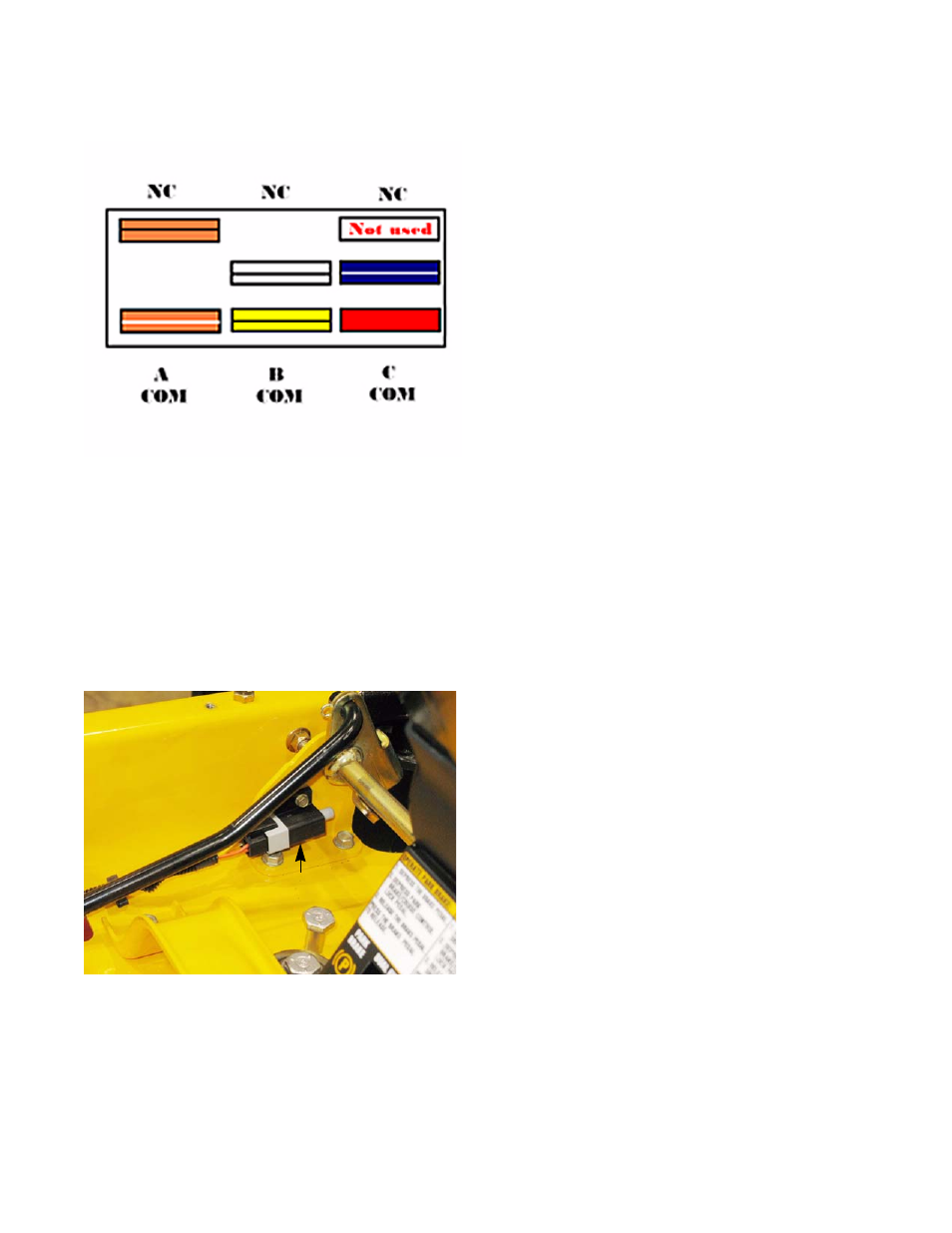
PTO Switch
Understanding the PTO switch
1. A-COM is in the starter circuit. It is a Normally Closed
(NC) set of contacts. Power coming from the brake
switch (key switch in START, brakes ON) flows
through the orange wire with black trace to the PTO
switch. When the PTO is OFF, and the contacts are
closed, the power continues through the orange wire
with white trace to the trigger terminal on the starter
solenoid.
2.
B-COM is in the PTO relay latch circuit. It is a Nor-
mally Opened (NO) set of contacts. The yellow wire
with a black trace is connected to the coil of the PTO
relay. When the PTO switch is in the “ON” position,
the yellow wire with a black trace is connected to the
white wire with a black trace. If the PTO relay is ener-
gized, a ground signal will pass through the white
wire with a black trace to the yellow wire with a black
trace keeping the relay energized.
3.
In C-Com, power is supplied to the PTO switch from the L terminal of the ignition switch through a red wire.
When the PTO switch is turned ON, this completes the circuit to allow power to go to the PTO clutch. It is a
normally opened (NO) set of contacts.
NOTE: The top terminals are showing normally closed at rest and the middle terminals are normally open at
rest
NOTE: There are three contacts on the right side in the C-COM. For this application the normally opened (NO)
contact is used.
Brake Switch
The brake switch the left brake pedal shaft support bra-
ket. See Figure 7.3.
• The plunger on the switch is depressed when the
brakes are applied. The switch contains two sets
of contacts.
• A normally open (NO) set of contacts is in the
starter circuit. When the brakes are applied, the
contacts are closed. Power coming from the key
switch (key switch in START) through the orange
wire is passed on to the PTO switch through the
orange wire with black trace.
• A normally closed (NC) set of contacts is in the
safety shut-down circuit. The yellow wire with a
white trace carries a ground signal from the seat
switch (seat is empty). Setting the parking brake
closes the contacts, passing the ground signal
through the yellow wire to the magneto primary
windings.
• The yellow wire with a white trace leads to one ele-
ment of the seat switch. If the seat is vacant and
the pedal is up, the engine will turn off.
Figure 7.2
Figure 7.3
Brake switch